Basic
Highway Plan
Reading
Inspector
ualification
Series
FORWARD
This Plan Reading Course is to present a step-by-step procedure on how to read,
interpret, and relate to a standard set of roadway plans; to help identify and interpret
symbols used in a standard set of plans; and to help develop the necessary skills to
interpret a set of plans in non-technical terms to laypersons (property owners and
others). Along with this manual you will use plan sheets & standards that specifically
relate to it. The plan sheets/standards included have been reduced to half their original
size so they can be handled more easily.
Since it is our intent to provide you with a well rounded exposure to highway
construction plans, you may be asked to look at a plan sheet from a particular project.
Please ascertain that you are looking at the correct set of plans for the text that you are
reading and the questions you may be asked to answer.
TO THE STUDENT
This is a self-instructional study course. The subject matter is arranged so that you may
work at your own speed. Each part of the course builds on the information that has
preceded it, and prepares for information to follow. Most of the parts present new
information. Some parts review important facts that have been introduced to you earlier
in the program.
The idea behind this method is for you to read and study the information, actively
participate by writing or checking off answers to questions, then find out immediately if
you are correct. This method reinforces what you have read and enables you to retain
what you have learned for a longer period of time. The retention of information from a
self-instructional study course should be far greater than from a lecture or textbook.
To get the most from this course, start at the beginning. Read each section as it comes
preparing you for the next section. To make reading easier, the information is divided
into frames. At the end of some frames, you will find questions. By answering these
questions, you will be able to retain what you have just read longer than by lecture or
discussion. The answers to these questions are at the end of this document.
TABLE OF CONTENTS
Chapter 1: Beginning to Read Plans
Chapter 2: Typical Sections
Chapter 3: General Notes
Chapter 4: Summary of Approximate Quantities & Tabulation Drawings
Chapter 5: Views
Chapter 6: Stationing and Symbols
Chapter 7: Plan and Profile Sheets
Chapter 8: Drainage and Structures
Chapter 9: Utilities
Chapter 10: Signing & Pavement Markings, Signals, Highway Lighting & Landscaping
Chapter 11: Maintenance of Traffic, Sequence of Operations and Staging
Chapter 12: Stormwater Management Plan (SWMP)
Chapter 13: Cross Sections
Chapter 14: Standards and Details
Chapter 15: Right of Way
CHAPTER 1: BEGINNING TO READ PLANS
GENERAL INFORMATION
A requirement occurring in one of the parts of a Colorado DOT contract is as binding as
though occurring in all. The Standard Specifications, Supplemental Specifications,
Plans, Special Provisions, and other supplementary documents are all part of the
contract. In case of a discrepancy, certain parts of the contract govern over others
pursuant to subsection 105.04 of the Standard Specifications.
Supplemental Specifications govern over Standard Specifications; Plans govern over
Supplemental Specifications and Standard Specifications; Detailed Plans govern over
the Standard Plans; Standard Special Provisions govern over Plans, Supplemental
Specifications, and Standard Specifications; and Project Special Provisions govern over
Standard Special Provisions, Plans, Supplemental Specifications, and Standard
Specifications.
In the event such errors or omissions are discovered, the Engineer will then make such
corrections and interpretations, as may be determined necessary for the fulfillment of
the intent of the Contract.
The Specifications contain all directions, provisions and requirements pertaining to
performance of the work. They describe the materials and construction requirements in
sufficient detail to allow for accurate and competitive bids. They also include contract
management details that allow CDOT to control the contract.
The specifications cover the Bidding Requirements and Conditions, the Award and
Execution of the Contract, the Scope of Work, the Control of the Work, the Control of
Material, the Legal Responsibilities to the Public, the Prosecution and Progress of the
work, the Measurement and Payment, the Construction Details, and the Materials
Details.
The outline used for the Construction Details sections 200-600 is:
1) Description
2) Materials
3) Construction Requirements
4) Method of Measurement
5) Basis of Payment
The Plans are drawings comprised of the Standard Plans and Detailed Plans
provided by the department, which show the location, character, dimensions, and
details of the work.
The Standard Plans (M&S Standards) simplify the design process by detailing
standard design and construction practices which are utilized on all projects. This
provides for uniformity, cheaper prices, and higher quality on CDOT projects. Examples
include guardrail, inlets, signs, striping.
The Detailed Plans show the specific requirements and qualities of an individual
project. For example, project location, general notes, typical section, items and
quantities, plan sheets, tabulation sheets, structure details, sign quantities, and details
for items not included in the Standard Plans.
The Standard Special Provisions are comprised of additions and revisions to the
Standard Specifications that are included as appropriate on a group of projects.
Sometimes they apply to all projects.
The Project Special Provisions are comprised of revisions to the Standard
Specifications that are specific to a particular project.
Why do we have Standard Plans and Standard Specifications? The most obvious
reason is to ensure uniformity and quality of construction on our projects. The other is
that, on projects with FHWA oversight, the plans, specifications and estimate for each
project must be approved by FHWA prior to advertisement. In the absence of pre-
approved standard specifications and standard plans, all of the required specifications
and plan information would have to be included and approved in each package
submitted to FHWA. Once Standard plans and specs have been approved by FHWA
they may be used on Federal Aid projects without further review.
When the Plans for a contract are completed, the sheets are normally placed in a
specific order. (The following list is used as a general guide and is sometimes changed
to better fit an individual project).
x Title Sheet
x Index (Generally included on the Title Sheet)
x M&S Standard Plans List
x Typical Sections
x General Notes
x Summary of Approximate Quantities
x Structure Tabulation
x Earthwork Summary
x Surfacing Tabulation
x Guardrail/Fencing/Delineator Tabulation (Included on separate sheets on large
projects)
x Plan and Profile Sheets
x Interchange Plan Sheets
x Profile of Ramps or Sidestreets or Driveways
x Bridge Plans and Details
x Retaining Wall Plans and Details
x Structure Cross Section (Culvert Profiles)
x Stormwater Management Plan
x Wetland Mitigation Sheets
x Utility Plans
x Phasing and Detour Plans
x Traffic Control Plans
x Permanent Signing & Marking Plans and Details
x Traffic Signal Plans and Details
x Lighting Plans and Details
x Survey Tabulation
x Control Survey Diagram
x ROW Plans
x New and Revised M&S Standards
x Earthwork Cross Sections
TITLE SHEET
The front sheet of a set of plans is called the TITLE SHEET. The information shown on
it is:
x Project name
x Project number
x Project code number (PCN)
x County
x Project location map
x Box containing revisions
x Project limits and length
x Route Number
x Signature Boxes for those responsible for the Design of the Plans
x Signature Box for the Chief Engineer or Responsible Official
x Date the Plans were completed
x Professional Engineer's Stamp
x Index
Turn to the TITLE SHEET, Plan Sheet #1 and see how many of the above features you
can identify on your own.
DESCRIPTION
Looking at your set of Plan Sheet #1 you should have found this project name:
Foxton Road to Eagle Cliff Road
PROJECT LOCATION MAP
In the center of the Title Sheet is a LOCATION MAP. This view shows the beginning
station and the ending station of the project, and other features to help identify the
location.
SHEET IDENTIFICATION-TITLE BLOCK
Now look at the lower edge of the Title Sheet. Each sheet in a set of plans has a similar
box for standard identification for each sheet. The box lists the project number, project
code number, the Plan Sheet number, Sheet Revisions, designer and computer file
information, and the plan sheet name.
PLANS REVISED AND PLANS COMPLETED
A box is provided on each plan sheet to list each time the plan sheet has been revised.
A date is placed in the box for each of these occurrences.
SCALE
Roadway plans are drawn to scale in order that they might be presented on easy-to-use
sheets. Roadway plans are normally drawn with an engineer’s scale. Structure plans
are generally not drawn to scale.
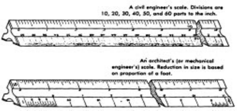
The engineer’s scale is one that expresses scale as 1 inch = 10 feet, 1 inch = 20 feet, 1
inch = 50 feet, 1 inch = 1 mile, etc. It is usually 1-foot long and may be triangular or flat.
The scales are divided into decimal parts of an inch such as 1/10th inch, 1/20th inch,
etc.
The triangular, or six-scale scale, has scales with 10, 20, 30, 40, 50, and 60 divisions to
the inch.
The scale on which the Title Sheet was plotted is shown graphically on the Title Sheet.
Plan sheets, however, are plotted on various scales depending on the need for detail,
etc., and are notated as such on the respective plan sheets.
PROJECT LENGTH AND DESIGN DATA
A Tabulation of Length and Design Data box is shown on the Title Sheet noting the
approach to project, length of the project, bridges and no-work areas, when applicable.
In the design of a highway, traffic data is used to determine the number of lanes and the
depth of paving. This data is shown in this box as well.
INDEX OF SHEETS
An index of sheets is required for each set of construction plans to help the user in
identifying what sheets are in the set of plans. The index is normally included on the
cover sheet, but may be a separate sheet directly following the title sheet.
Answer the questions concerning the title sheet:
1-1 What gives you the basic description of the project?
1-2 What gives you the beginning and ending of the project?
1-3 Where is the location of the project shown?
Using Plan Sheet #1, answer the following questions:
1-4 What is the name of this project?
1-5 What is the total gross length of this project in miles?
1-6 On what sheet numbers would you find the retaining wall plans?
CHAPTER 2: TYPICAL SECTIONS
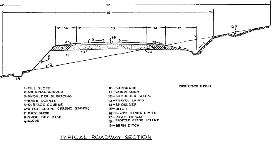
The typical section is a picture, with dimensions, of how the cross sectional view of the
roadway would appear after the construction is completed. Following is an idealized
roadway typical section with the various elements identified. Study the drawing and
become familiar with the various items.
Look at Plan Sheet #2 and find some of the significant features you should know about
this Typical Section:
1. This is a four-lane divided roadway with a median
2. The traveled way for each side of the roadway is 24 ft. wide, with two 12 foot
lanes.
3. There is a four foot paved inside shoulder and a ten foot paved outside shoulder.
4. The profile grade point is at the centerline of roadway.
5. The location where the typical section is to be used is shown. (normally shown
directly under the typical section, not shown on Plan Sheet #2)
6. Paving requirements are also spelled out. (the type of roadway structure section)
7. Notes are added for clarification.
HORIZONTAL DISTANCE
The dimensions shown on the Typical Sections are horizontal dimensions. This means
that the distances are not measured along the slopes of the roadway. For example, the
distance from the profile grade of the left lane of the Typical Section to the edge of the
pavement is written as 24. The slope distance measured along the actual surface would
be slightly longer than 24. All the dimensions shown by level lines are Horizontal
Distances. Explanations of Slopes will be discussed later in this book.
Use Plan Sheet #2, Tangent Section, and answer the questions:
2-1 What is the total thickness of the concrete pavement?
2-2 What is the thickness of the ABC leveling course used under the concrete
pavement?
2-3 How wide is the median?
2-4 What is the total width of the concrete pavement for the northbound lanes?
CHAPTER 3: GENERAL NOTES
The General Notes sheet contains a list of notes that clarify items that are not
satisfactorily covered elsewhere in the specifications or plan details. On smaller
projects, a page of general notes include the majority of all plan notes. On larger
projects each specialty (i.e., bridge, traffic, landscaping) may contain its own area of
general notes. This section may contain notes that describe pay items that do not
require a tabulation, such as Clearing and Grubbing, Construction Surveying, and
Mobilization. Typical notes instruct the Contractor as to how the HBP quantities were
calculated, incidental items of work, tack coat application requirements, ROW access
restrictions, pavement smoothness requirements, the type of compaction required, and
items of work that are not listed on other plan sheets.
Use Plan Sheets #3, General Notes, and answer the questions:
3-1 What is the type of compaction to be used for this project?
3-2 What is the smoothness category for concrete pavement to be used on the project?
3-3 How many sanitary facilities will be required?
CHAPTER 4: SUMMARY OF APPROXIMATE QUANTITIES &
TABULATION DRAWINGS
SUMMARY OF APPROXIMATE QUANTITIES
The Summary of Approximate Quantities plan sheet shows all the pay items of work
that are included in the Contract. The items are listed in numerical order by item code.
Use Plan Sheet #4 to answer the questions:
4-1 How many square feet of Sign Panel (Class I) is estimated to be required?
4-2 How many total linear feet of Fence Chain Link (Special) (36 inch) is needed?
4-3 How many linear feet of 2 inch Electrical Conduit is required for Structure #F-15-DJ?
TABULATION DRAWINGS
Tabulation drawings are used to tabulate specific pay items in regard to location and
offset. They are included in most project plans. All pay items must be either mentioned
in a general note or have a tabulation somewhere in the plans. A single tabulation
normally includes similar items. For example, a tabulation may list all locations of curb
& gutter, sidewalk, and curb ramps for the project.
Structure Quantities
The structure quantities sheet tabulates the minor structures such as culverts, inlets,
other drainage structures, and associated structure excavation and backfill. This sheet
is sometimes called the Tabulation of Drainage Items and is normally on its own sheet
in a set of plans.
Surfacing
The surfacing tabulation contains the quantities of various materials to be utilized in the
pavement structure and is also normally on its own sheet of the plans.
Fence, Guardrail, Delineator
The fence, guardrail and delineator tabulations are frequently combined onto one sheet
of the plans.
Removals and Resets
Removals and Resets are normally included in the individual tabulations for that item of
work. For example, pipe removals may be included on the Structure Quantities sheet
and guardrail removals are included in the Guardrail Tabulation. However, sometimes
all or most removals and resets are combined into one sheet.
Use Plan Sheets #5 and #6 to answer the questions:
4-4 How many square yards of Concrete Pavement (10 inch) is required between Sta.
116+50 and Sta. 119+50 Rt.?
4-5 What length of 24 inch culvert pipe is required at Station 85+00 Lt.?
4-6 What type of embankment protector is required at Station 114+48 Lt on the
Kennedy Gulch Access Road?
CHAPTER 5: VIEWS
Before going any further, you need to know more about the different viewing angles
from which various things are shown in a set of plans. A view is the way you look at or
see the different items that are shown on a set of plans.
A view may show something observed from the inside or from the outside. These views
are drawn to give you clear and complete pictures of how the fence, pipe, ditch, culvert,
etc., should be built or placed. To get the information you need, you must be able to
look at the view and see what is being pictured. You need to know from which angle the
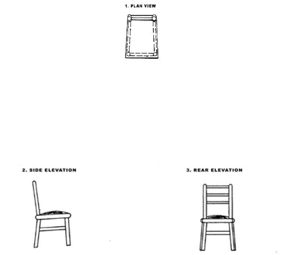
item is shown. To help you see the different views, a chair will be used as the object pic-
tured because of its familiarity to the reader.
The views here show this chair in the same way that the real views show things more
appropriate to road and structure building.
A Plan View is a view from directly above the object. A top view looking down on a chair
is pictured. Dotted lines show parts of the chair you would not see because the seat
would hide the legs and crosspieces and you would not see them.
Now look at the set of plans you were given with this material. The first sheet, cover
sheet, shows a Plan View of the entire project. If you were flying in an airplane, high
over this project and looked down, the plan view is what you would see.
The next set of views shows the elevation or height of the chair from the side and rear.
The view might also be shown from the other side or from the front.
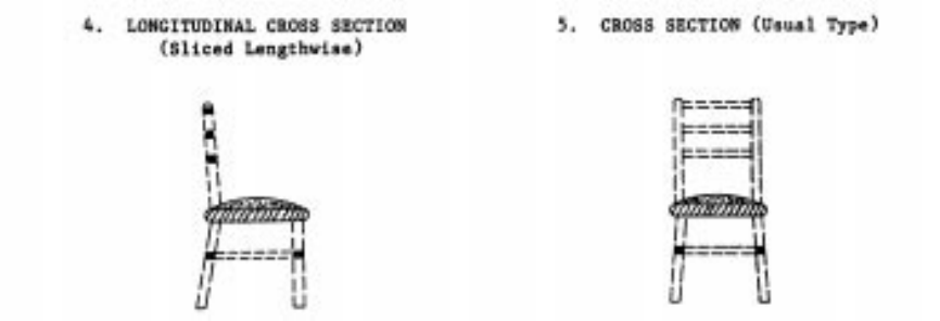
CROSS SECTION
As you face the front of the chair, a section has been sliced away. Here the chair was
sliced across the seat. You see the layers of the cushion and seat inside the seat. The
rest of the chair, shown by dotted lines, is behind the point where the slice was made.
LONGITUDINAL CROSS SECTION
As you face the side of the chair, a section has been sliced away. You see the inside of
the seat from the side. Also note the inside of the crosspieces at the top and bottom of
the chair.
PROFILE VIEW
A Profile View is a lot like a longitudinal cross section of the roadway. Rather than left to
right, the profile view shows the hills & valleys of the roadway running along the
centerline of the road. It’s how the road would look if you were actually riding on the
surface of the road. (Profile view will be further discussed in another chapter.)
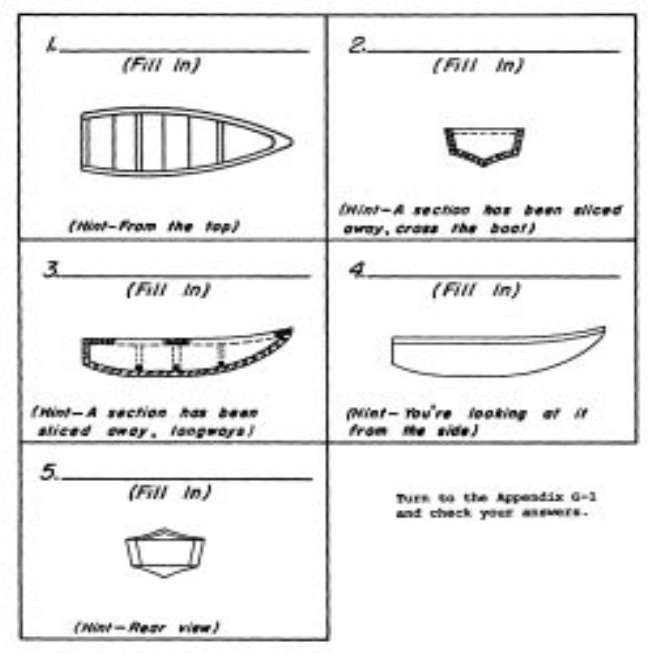
5-1 Below is a drawing of an old boat. Five of the six views mentioned previously, are
shown on it. Write the name of the view above each drawing.
Of course, the actual views on a set of plans also give dimensions, materials used in
construction, and many other construction details.
The ELEVATIONS generally show the items from the OUTSIDE. These views are
usually very clear drawings, almost like a picture.
The CROSS SECTIONS always show an inside view where something has been sliced
away to show you how the inside part should be. These slices may be made at any
point and would be compared to cutting an apple into two parts with a knife. The next
pages show you how you can sometimes tell where the section is or where the cut was
made.
Suppose, for example, sections of a pencil were used to show the inside materials at
different places along the length. See how this is shown in the drawing. The lines
between the letters A-A, B-B, and C-C show where the section is taken. The arrows on
the ends of the lines show which way you’re looking toward when you look at the
section.
The sections are labeled, A-A, B-B, and C-C, etc., to correspond with the letters on the
overall diagram, as shown here:
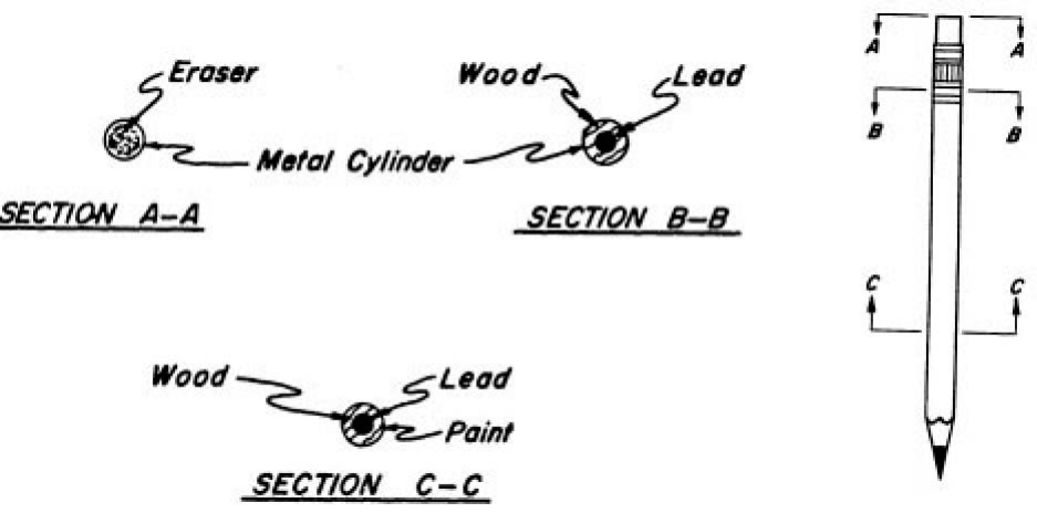
Using the drawing of the pencil, answer the questions:
5-2 Consider the eraser end the back of the pencil and the pointed end the front. Is
section A-A looking toward the back or the front of the pencil?
5-3 What direction are you looking toward in Section B-B?
5-4 What direction are you looking toward in Section C-C?
5-5 In Section C-C, what material is shown in the center of the pencil?
CHAPTER 6: STATIONING AND SYMBOLS
STATIONING
Since stationing is fundamental to highway plans, it is felt that a discussion of stationing
should be offered before you get involved with the plans. A station is the Horizontal
measurement along the Survey Center Line of a project. Distances are measured and
points are identified on plans with reference to Station Numbers. One hundred feet
make up a Highway Station. Highway stationing might be compared with a rope having
knots at 100-foot intervals. The beginning of the rope would be 0, the first knot at 100
feet would be Station number 1 and would be written as 1+00. The second station
number would be 2 (which is 200 feet from the beginning) and would be written as 2+00
and so on.
Station numbers usually increase from the beginning of the project to the end of the
project. Also, stationing usually runs from South to North or from West to East. The
beginning station of a project is usually arbitrary. Generally, it will be 10+00 or 100+00.
If there was a project for this road in the past, the beginning station number may be
much higher than the previous example.
Since all items on the plan refer to the Survey Center Line, any particular item can be
located by giving its stationing and the perpendicular distance left or right of the Survey
Line. The length of the project may be arrived at by subtracting the beginning station
from the ending station (making allowances for equations) and multiplying by one
hundred. An explanation of equations will follow.
For instance, if a project begins at station 650 (written 650+00) and ends at station 920
(written 920+00), the length is (920-650) X 100 = 27,000 feet. This can easily be
converted to miles by dividing by 5280 feet per mile.
Just as 12 inches make one foot, 100 feet make one station. It is 100 feet from Station
100 to Station 101 or from Sta. 493 to Sta. 494, etc. (see the following)
Answer the question:
6-1 How many feet make up a station?
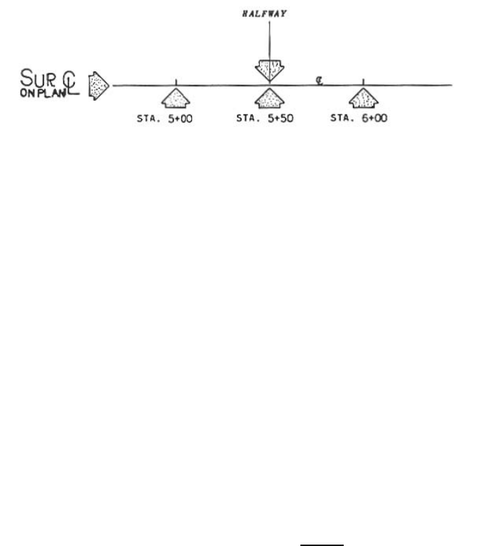
A half station is 50 feet and is located halfway between stations. It is written as +50 after
the station number. The example below shows you how station numbers and half
stations are written.
Any point between two stations is shown in this same way:
For example, two feet ahead of station 500+00 is written as 500+02. Numbers less than
10 are indicated as 01, 02, 03, etc. Ninety-nine feet ahead of station 500+00 is written
as 500+99. Of course, 100 feet ahead of Sta. 500+00 is Sta. 501+00.
In other words, to show that a point is exactly on a station, write it as +00. To find the
distance between any two stations (except where station equations or equalities are
involved) simply subtract the lower station from the higher one, ignoring the plus sign.
You will get the answer in feet.
Example: To find the distance from the Station 2060
20+60 to Station 12+80 you can -1280
write the numbers like this: 780
It is 780 feet from Station 20+60 to Station 12+80.
6-2 The distance between Station 48+76.2 and Station 51+24.8 is ________ feet.
6-3 The distance from Station 14+10 to 15+00 is ________ feet
6-4 The distance from Station 80+10 to 85+20 is _________feet
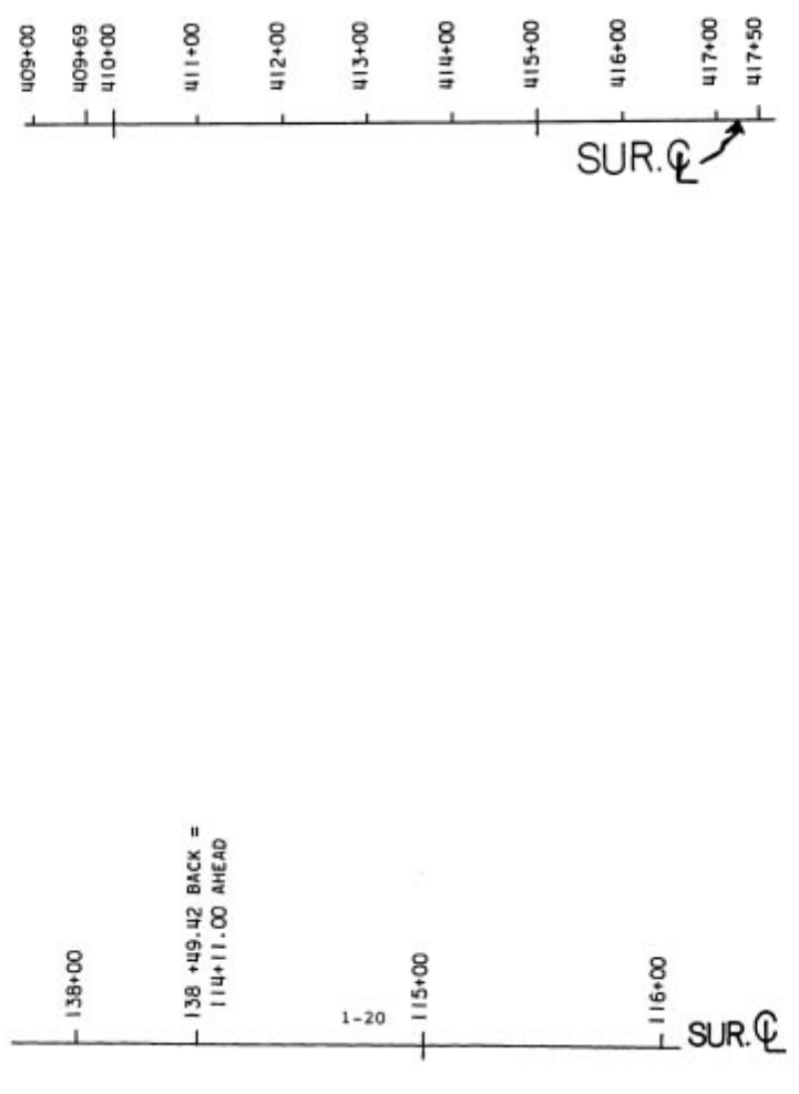
On the Plan Sheets, the Station Numbers are usually written along the Survey Line.
Stationing is sometimes along a baseline, or along one lane of a multiple lane highway.
On a project, AHEAD means in the direction in which Station Numbers increase.
(Usually toward the END of a project) BACK means in the direction in which Station
Numbers decrease. (Usually towards the BEGINNING of the project).
On a plan sheet, stationing would be similar to that shown above.
Answer the questions:
6-5 What is the Station Number of a point on Survey C/L 50 feet AHEAD of Station
412+00?
6-6 What is the Station Number of a point 50 feet BACK of Station 412+00?
Generally, station numbers progress (increase) from WEST to EAST or from SOUTH to
NORTH. Since highways curve and change direction, the above statement is not always
true on any one segment of the road. Just remember that when you say AHEAD you
mean toward a higher or up station. When you say BACK, you mean toward a lower or
down station.
STATION EQUATIONS
Sometimes it is necessary to relate a system of stationing to another system as the
connection between two projects or to account for an increase or decrease in the
projects length due to a change in horizontal alignment.
Equalities are written to describe a point on a survey line where the station numbers of
one system change to the station numbers of another system. Here is one equality:
Station 138+49.42 BACK = Station 114+11.00 AHEAD. The first number is the
stationing that is ending. The next number is the beginning station number.
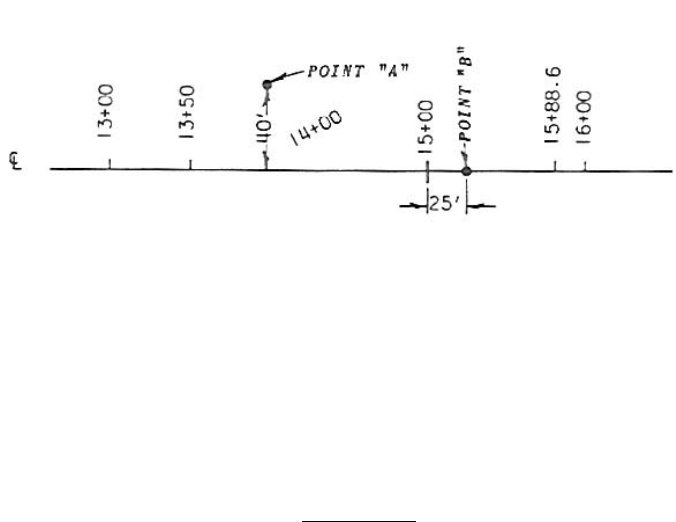
Any point pertaining to a project may be located on the ground and on the plans by its
Station and the number of feet (Offset) LEFT or RIGHT of the Survey C/L. Left and
Right of the survey C/L means as if you were facing ahead.
Answer the question(s):
6-7 If this station equation is given Station 550+00 BACK = 2+00 AHEAD: a) What is
the Station Number of a point 50 feet BACK of the station? b) What is the Station
Number of a point 50 feet AHEAD of the station?
6-8 What is the station and offset location of point A on the previous sketch?
6-9 What is the station location of point B on the previous sketch?
DETERMINING THE PROJECT LENGTH
If there are NO STATION EQUATIONS on the project, you can subtract the beginning
station from the ending station and have the length of the project.
This project ends at station 701+50.00
This project begins at station 409+69.00
Equals the length of the project 291+81.00
Always remember that this length, 291+81.00 (or 291 x 100 ft/station +81) is the length
of the project only if no equalities occur between the beginning and the end of the
project. To determine the mileage in a project, you divide the feet in the project by 5280
ft. (the number of feet in a mile). In this case you would divide 29,181.00 by 5280 and
you would get 5.527 miles.
STANDARD SYMBOLS
A legend of symbols is included in the M&S Standard Plans. These symbols are utilized
to identify features on the plan sheets such as roadways, utilities, top of cuts, fence,
culverts, landscaping, and other physical features. Refer to M-100-1.
CHAPTER 7: PLAN AND PROFILE SHEETS
Roadway Plan Sheets depict all details of the project horizontal alignment. They may be
presented in conjunction with the corresponding profile on the lower half of the sheet
called a Plan/Profile Sheet, or the Profile Plan Sheets may be a separate sheet from the
Plan Sheet.
Existing features and roadway design elements such as pavement and shoulder widths,
medians, curbs, drainage elements, tapers, turning provisions, and intersecting
roadways are shown on these sheets. All horizontal geometry is depicted and labeled to
fully define the design intent. Separate Plan Sheets may be required for details, which
cannot be adequately shown on the Roadway Plan Sheets.
Both separate Plan & Profile Sheets and combination Plan/Profile Sheets give a view of
the entire project. They both begin with the lowest station number and the beginning of
the project and show the entire roadway ahead to the end of the project.
PLAN VIEW
Remember that a PLAN VIEW shows the roadway as if you were flying high over the
project and were looking down. Turn to Plan Sheet #7. On this Plan Sheet, the
PAVEMENT LINES (edges of the pavement) are shown. You can also see the SURVEY
CENTER LINE running from the left of the sheet AHEAD to the right of the sheet, then
continuing on to the next plan sheet. Above survey C/L, on the Plan Sheet, is
considered left of the Survey Line. Below the survey C/L is considered right of the
Survey Line. Either case will be as though you were standing on the Survey Line facing
ahead.
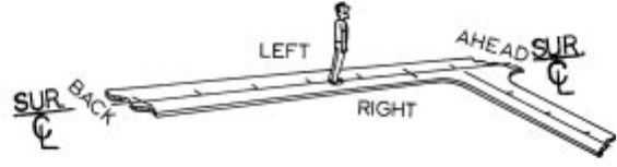
Remember that throughout this course and when speaking of plans that LEFT refers to
left of the Survey C/L and RIGHT refers to the right of the Survey C/L, as shown in the
previous drawing, not the left and right side of the Plan Sheet.
On all construction plans and right of way plans, there is an arrow-like symbol with the
point indicating North.
The direction of all control and boundary lines is in reference to this North arrow.
The direction of a Survey Center Line as you are advancing in stationing, as expressed
by a bearing, defines the relationship between the direction of the survey line and a
North-South line. It is customary to orient drawings so that the North direction is to the
TOP of the plan. However, since plans for a complete highway project can seldom be
confined to a single sheet, and must be a series of sheets, it is an accepted practice to
make the plans to extend from left to right without regard to the North direction. Look
again at Plan Sheet #7 and see the NORTH ARROW. Remember that Station Numbers
normally increase from SOUTH to NORTH. On this plan sheet, the stations “65”, “70”
and “75” are shown above the centerline. Note the 100-foot tick marks on the survey
line indicating intermediate stations between the larger 500-foot tick marks.
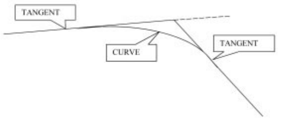
HORIZONTAL ALIGNMENT
Horizontal Alignment consists of tangents and curves and is shown on the Plan View.
Plan Sheet #7 shows the Horizontal Alignment. Plan Sheet #8 shows the Vertical
Alignment or Profile View of the same section of roadway. (Vertical Alignment will be
discussed more later.)
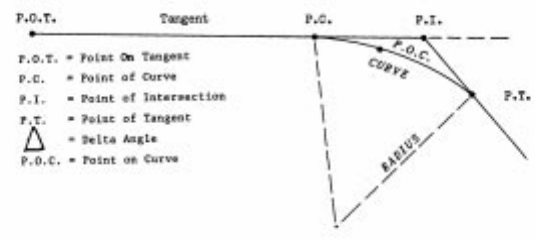
Tangent: A straight segment of roadway
Curve: Segment of roadway joining two tangent segments
Point of Curve (PC): The beginning of a curved segment of roadway
coming from a tangent.
Point of Tangent (PT): The point at the beginning of a tangent section of
roadway coming from a curve
Point of intersection (PI): The point where 2 tangents intersect
Point on Tangent (POT): A point on a tangent (straight) segment of roadway
Point on Curve (POC): A point on a curved segment of roadway
Point of Tangent to Spiral (T.S.): The beginning of the spiral curve segment of roadway
coming from the tangent.
Point of Spiral to Tangent (S.T.): The point at the beginning of a tangent section of
roadway coming from a spiral curve
Point of Spiral to Curve (S.C.): The point at the beginning of the curve coming from a
spiral curve.
Point of Curve to Spiral (C.S.): The point at the beginning of the spiral coming from a
curve.
Tangent Distance (Tc or Ts): The distance measured from the P.C. (point of curve)
or P.T. (point of tangent) to the P.I. (point of
Intersection). In the case of a spiral curve, the
distance measured from the T.S. or S.T. to the P.I.
Length of Curve (Lc): The distance measured along the curve from the P.C.
(point of curve) to P.T. (point of tangent)
Length of Spiral Curve (Ls): The distance measured along the spiral curve from
the T.S. to S.C. (point of spiral to curve)
Degree of Curve (Dc): The angle subtended at the center of the curve by an
arc 100 feet long.
Delta Angle: The angle that intersects between the forward and
back angle.
Superelevation: The rotating pavement surface slope to compensate
for centrifugal force in a curved segment of roadway.
Superelevation Rate (e): Percent slope required on a pavement surface in a
curved segment of roadway
SPIRAL CURVES are sometimes used for the purpose of connecting a tangent with a
circular curve in such a manner that the change of direction and elevation from one to
the other takes place gradually. A spiral is a curve in which the degree of curve
increases linearly with the length of curve measured from the point where the curve
leaves the tangent. The degree of curve is zero at the point the alignment changes from
tangent to spiral (T.S.) and at the point at which the spiral meets the circular (S.C.), it is
equal to the degree of circular curve.
True or False
7-1 True False. A tangent is an arc or segment of a circle joining two lines.
Turn to Plan Sheet #7 and see the CURVE DATA in the upper center part of the sheet.
Note this is a Spiral Curve. See explanation below.
P.I. = 67+19.94 Point of Intersection (The place where two tangents intersect.)
D = 05º 15’00” Degree of Curve (degrees, minutes, seconds)
Ts = 756.29’ Tangent Distance (T.S. to P.I. & P.I. to S.T.)
Lc = 768.37’ Length of Curve (P.C. to P.T.)
Ls = 320.00’ Length of Spiral Curve
e = 0.06 ft/ft Superelevation Rate
Turn to Plan Sheet #7 and answer the questions:
7-2 At what station does the spiral curve begin? _______________
7-4 What is the degree of curve for this curve? _______________
SUPERELEVATION
Superelevation of curves may be defined as the rotating of the roadway CROSS
SECTION in such a manner as to overcome the centrifugal force that acts on the motor
vehicle while it is traversing curved sections. In other words, when you are in a curve,
your car tends to be thrown to the outside of the curve. So, in order to overcome
centrifugal force, it is obvious that the normal roadway cross section will have to be
tilted to the superelevated cross section. This tilting is normally accomplished by means
of rotating the cross section about the inner edge of the pavement or the about the
centerline axis.
Review sheets M-203-10 through M-203-13 for superelevation standards.
BEARINGS
A bearing is a method used to express direction. Bearings are used on a set of plans to
indicate the direction of the Survey C/L and the direction of other survey lines and
property lines.
The bearing is described as so many degrees, minutes, and seconds in the direction in
which the line is progressing. The accuracy of calculations are dependent on exact
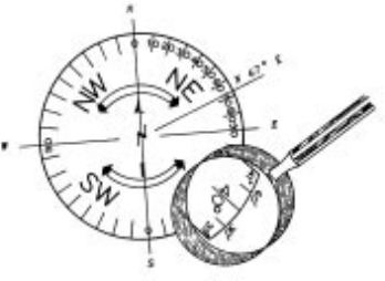
measurements of distances and bearings. A bearing might be written as N 65º 15’ 30’’
E.
There are 360 degrees in a full circle. There are 60 minutes for each degree and 60
seconds in each minute. When shown as a compass circle, the circle is divided at
North, East, West, and South points into four sections of 90 degrees each. The four 90
degree sections are called QUADRANTS and designated: Northeast (N.E.), Northwest
(NW), Southeast (SE) and Southwest (SW). This is illustrated by the drawing, which
follows:
Bearings are the angular measurements of a line running East or West of due North
and East or West of due South. Highway bearings do not go beyond 89º 59’ 59”, which
is read as 89 degrees, 59 minutes, 59 seconds. After the aforementioned bearing, they
are either due East or due West, or in another quadrant.
Answer the questions:
7-5 There are ________________ degrees in a full circle.
7-6 A bearing is used to express __________.
Answer the question using Plan Sheet #7
7-7 What is the bearing of the Survey Centerline Sta. 75+00? _______________
VERTICAL ALIGNMENT (PROFILE GRADE)
Now turn to Plan Sheet #8. Look at the profile shown on the sheet. The next few pages
in this book are about the VERTICAL ALIGNMENT or PROFILE GRADE.
A profile is like a longitudinal cross section of the roadway, rather than the left to right
width of the roadway. The profile shows vertical alignment along the roadway at the
centerline, survey line, construction centerline, or another point. The cut or fill on the
point shown on the profile does not necessarily mean that the cut or fill will be the same
at this or at any other point on the cross section. For instance, the left side of the
roadway might be in a cut section while the right side might be in a fill section.
On the Profile View, a heavy dark solid line usually shows the Profile Grade Line. It is a
regular and smooth line, just as the top of the roadway will be when finished being built.
Look at the Profile Grade Line in the bottom section of Plan Sheet # 8. The Existing
Ground Line is usually shown by a dashed line and is very irregular since the original
ground is irregular (or bumpy) before construction begins.
The primary purpose of the Profile Sheet is to show the relationship between the
proposed Profile Grade and the Original Ground Line.
Circle the correct answers:
7-8 Another name for profile grade is (vertical alignment / horizontal alignment).
7-9 A profile can show the vertical alignment along the roadway at the (centerline /
cross over).
ELEVATIONS
Elevations are given in feet above an arbitrary datum plane (usually sea level). These
are numbers shown on the right and left edge of the Profile Sheet. Looking at Plan
Sheet #8 look at the station numbers at the bottom of the page. Note that these
numbers are elevations (in feet) above sea level.
The engineers set reference points of known elevations so that they measure
differences in elevations (vertical distances). Sometimes, markers will be set and their
elevations determined and recorded. These markers are called BENCH MARKS(BM)
and are shown by Numbers (BM #1, BM#2, etc.) These Bench Marks are normally
identified on the Survey Control Sheet.
GRADE
Grade is the slope of the roadway with a vertical rise or fall expressed as a percentage
of the horizontal distance. That is, a +3% grade means a rise of 3 feet per 100 feet of
horizontal distance.
The grade is considered to be + (positive) or - (negative) depending upon whether it
rises or falls as you proceed along the grade line in the direction of increasing stations.
Circle the correct answers:
7-10 Elevations are given in (feet / yards).
7-11 The elevation numbers are shown on the (bottom / left & right) edge of the Profile
Sheet.
7-12 Reference point markers of known elevations are called (ground points / bench
marks).
Look at Plan Sheet #8 and answer the question:
7-13 What is the profile grade at Sta. 85+00? _______________
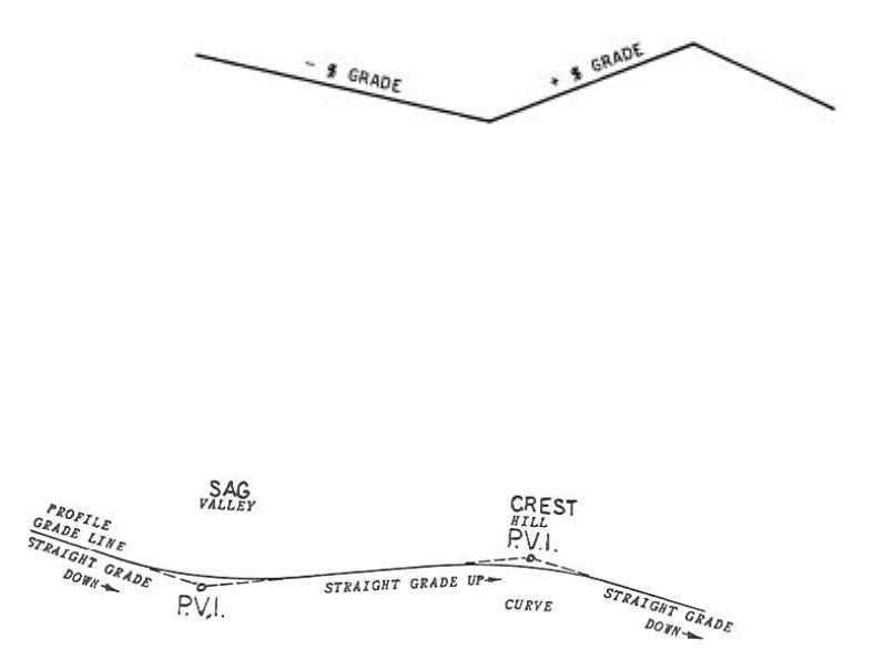
VERTICAL CURVES
When a road goes over a hill or mountain, it must curve over the top, (crest), or, if it
goes down in a valley (sag), it will curve as shown in the next drawing. These are
vertical curves and are shown on the Profile Sheets.
A small circle at the intersection of the tangents shows the P.V.I. or Point of Vertical
Intersection. The P.V.I. is similar to the P.I. (Point of Intersection) of a horizontal curve.
Look at the P.V.I.s on the previous sketch. Notice that the P.V.I.s are never on the
actual grade. They will be either above or below grade.
Look at Plan Sheet #8 at and answer the question:
7-14 What is the length of the vertical curve shown? __________
CONSTRUCTION ITEMS
In addition to showing the Horizontal and Vertical alignment discussed in the preceding
sections, the Plan and/or Profile Sheets contain a picture and a description of the work
to be done on the project. In the following section, you will be given examples of items
to locate on the Plan Sheet, Profile Sheet, or other sheets in the plans. Use Plan Sheet
#7 to locate some of the following items of work.
PAVING LIMITS
Paving limits are the LENGTH AND WIDTH of the roadway to be paved. The Tabulation
of Surfacing quantities sheet contains the location, type, and quantity of surfacing
needed.
CONSTRUCTION LIMITS
The Construction Limits of grading represent either the toe of fill or the top of cut slopes
showing where the limits of the construction should be. These limits of grading are
usually shown as dashed lines on the plans. See M-100-1 for these Standard Symbols.
FENCING
Fencing is a physical barrier to enforce observance of acquired access rights. As a
secondary function, fences may act as property fences or barriers to prevent the
indiscriminate crossing of medians. A separate Fencing Plan may be included in a set of
plans if the amount of fence warrants it. In most plans, fencing is pictured on the Plan
Sheets, as any other construction item would be, however, the quantities and locations
are listed on the Fencing Tabulation.
GUARD RAIL
The exact station location where the guardrail is required is not normally shown on the
Plan Sheets, but it is pictured in its general location. The Tabulation Sheets show the
exact location, type, quantity, etc. of the guardrail needed.
CHAPTER 8: DRAINAGE AND STRUCTURES
Project drainage is accomplished by means of ditches, pipe culverts, box culverts,
bridges and incorporating, where needed, minor drainage structures such as drop inlets,
man-holes, headwalls, etc. The amount of water to be drained determines the type and
size of drainage structure(s) to be built.
A culvert is a structure not classified as a bridge that provides an opening under a
roadway, usually for water drainage.
A bridge is a structure, including supports, erected over a depression or an obstruction,
such as water, highway, or railroad, and having a track or passageway for carrying
traffic or other moving loads and having a length measured along the center of roadway
of more than twenty (20) feet between abutments or extreme ends of openings for
multiple boxes. Each drainage structure is pictured in the Plan Sheets. Also included in
the plans will be a longitudinal cross section view of each of the drainage structures to
be installed.
PIPE CULVERTS
On Plan Sheet #7 at Station 69+80, a 24 inch culvert pipe is required. Find the listing
for this pipe on the Tabulation of Drainage Items, Plan Sheet #6. A headwall is required
on the inlet end and a flared end section with rip rap on the outlet end.
Circle the correct answers:
8-1 Drainage structures (are / are not) pictured in the Plan /Profile Plan Sheet
8-2 A bridge is a structure having a span length (over / under) 20 feet.
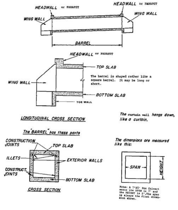
BOX CULVERTS
You need to know the names of the different box culvert parts. Examine the following
diagrams very carefully. Note: CDOT normally refers to a curtain wall as a toe wall.
You should be aware of the fact that culverts can also be built with more than one
barrel.
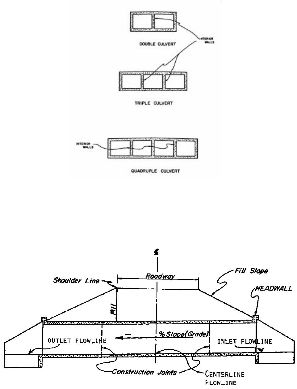
Using the previous drawings, answer the questions:
8-3 What are the three MAJOR parts of a box culvert?
8-4 What hangs down below the bottom slab at each end of the barrel? _____________
8-5 Is the horizontal or vertical distance considered to be the box culvert SPAN? _____
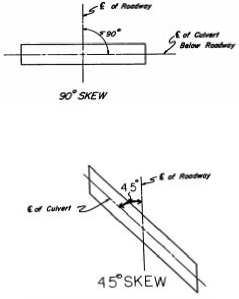
Shown above is a LONGITUDINAL CROSS SECTION of a BOX CULVERT.
Notice these things particularly:
a. The water goes in the INLET and flows to the OUTLET end of a culvert. The
INLET end is always HIGHER than the OUTLET end.
b. The CENTERLINE FLOWLINE is the elevation of the top of the bottom slab at
the centerline of the roadway.
c. The PERCENT OF SLOPE for the culvert BARREL is shown in the longitudinal
section on the drainage cross section sheet. It is established from elevations set
for the inlet and outlet elevations.
d. The FILL SLOPE is controlled by the height of fill from the shoulder line to the toe
of the slope. See typical sections.
e. The CONSTRUCTION JOINTS show where one concrete pour may end and
another may begin.
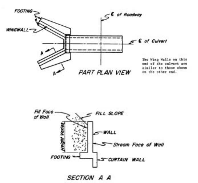
PLAN VIEW
Look at the PLAN VIEW shown below of the box culvert. Wing Walls and Headwalls are
not shown. This plan view shows the culvert from the top. See the centerline of the
roadway? Notice that the culvert is on a line perpendicular to the roadway centerline.
This culvert is said to be on a 90 degree SKEW.
This SKEW ANGLE is the angle that the centerline of the culvert makes with the
centerline of the roadway as measured in a clockwise or counterclockwise direction
from the centerline of the roadway looking ahead. Look at the next drawing of a 45
degree skew condition.
Using the preceding drawings of a culvert, answer the question(s) and/or choose the
right answer:
8-6 The end of the culvert that the water goes IN is called the _______________ end.
This is the (higher / lower) end.
8-7 The culvert slopes DOWN to the _______________ end.
8-8 A place at which one concrete pour may end and join another concrete pour is
called the _______________.
WING WALLS
Up to this point we have been concerned mostly with the box culvert barrel. Let’s look
now at the wing walls and their relationship to the barrel.
The purpose of wing walls is to keep the earth fill above the culvert from spilling into the
streambed. Below is a section of the wing wall on the previous drawing of a culvert.
Wing walls are extensions of the barrel walls that flare out away from the stream.
Shown next is a box culvert on a 60-degree skew. Notice how one wing is shorter than
the other.
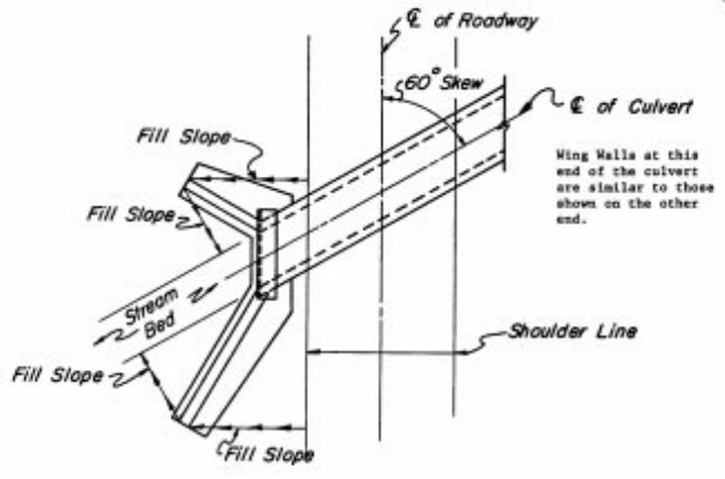
Notice that the length of each wing is such that the fill slope, as indicated by the
arrowed lines, proceeds down the slope from the shoulder line of the roadway, around
the end of the wing, and then down to the edge of the streambed. Therefore, the wing
lengths will vary from culvert to culvert depending upon the height of the culvert, the
slope of the fill, and skew of the culvert. Turn to M-601-20 and notice the lengths of the
wing walls. These varying wing lengths are examples of short and long wings.
The procedure of establishing the direction of the wings is shown on M-601-20. The
angle of the wingwall skew is normally measured from the roadway centerline bearing.
BRIDGES
Shown next are two views of a three-span bridge over a roadway. Look this structure
over carefully.
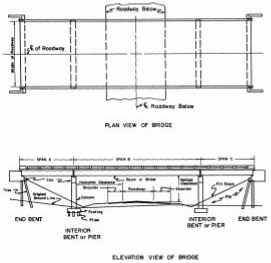
Notice these things particularly on the views of the bridge:
1. Look at SPANS A, B, and C. These Spans make up the riding surface of the
bridge and consist of a reinforced concrete deck (slab) supported on steel or
concrete BEAMS or GIRDERS that is supported on the end by BENTS. END
Bents are normally called ABUTMENTS, and interior bents are normally called
PIERS.
2. GIRDERS - These are placed lengthwise along the bridge parallel to the
Centerline of the Bridge as shown in the PLAN VIEW with each end resting on
the BENT CAP. They can be made of steel or reinforced concrete. They directly
support the roadway slab.
3. BENT – Is considered to be composed of the BENT CAP, COLUMN, FOOTING,
AND THE PILES.
4. BENT CAPS - These are constructed of reinforced concrete and are supported
either by means of concrete or steel PILES or of reinforced concrete columns.
5. FOOTINGS - These support the Columns and are constructed of reinforced
concrete. Footings are supported either on Piles or firm soil. Footings are not
seen once the bridge has been constructed since they will be covered with earth.
6. PILES - Piles are used when there is no firm material available to support a
footing. Steel piles are used in areas where rock is found; concrete piles are
used in areas where steel piles would corrode easily such as in coastal areas.
7. SUPERSTRUCTURE OF A BRIDGE - This is the part of the bridge that is above
the top of the bent caps.
8. SUBSTRUCTURE OF A BRIDGE - This is the part of the bridge that is below the
top of the Bent Caps.
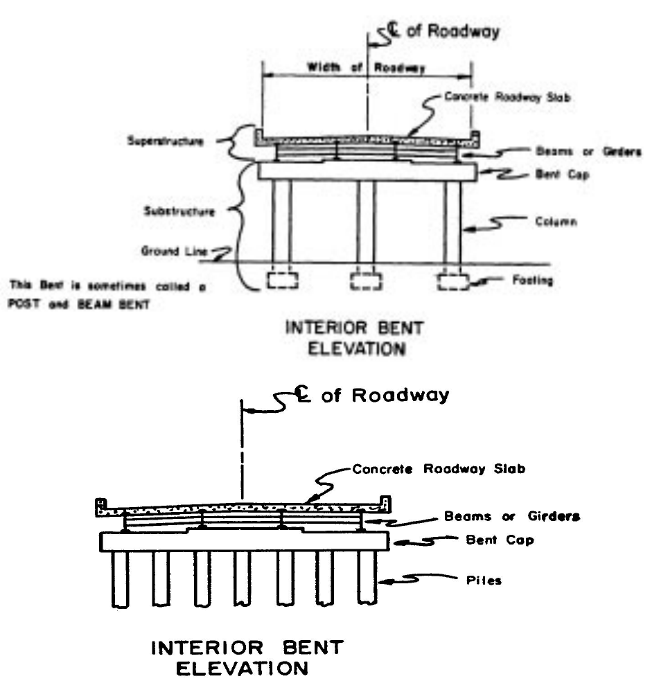
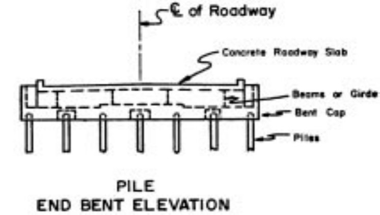
BENTS
The following are views of the most common types of Interior and End Bents that you
will find in structure plans. The views show what you would see if you cut a section
across a bridge between bents. Bents are normally numbered in the direction of
Stationing. For example, if the structure has two abutments and two piers, they would
be numbered on the plans as, Abutment 1, Pier 2, Pier 3, and Abutment 4.
Using the previous drawings and information, answer the question(s):
8-9 The two main parts of a bridge are _______________ and _______________.
(Hint: Above & Below Bent Cap)
8-10 Depending on the ground, Bent Footings may be supported in two ways. These
are _______________ or _______________.
8-11 What are the two types of piles normally used? _______________ and
__________________.
8-12 What two materials are beams or girders made of? _______________ or
_______________ .
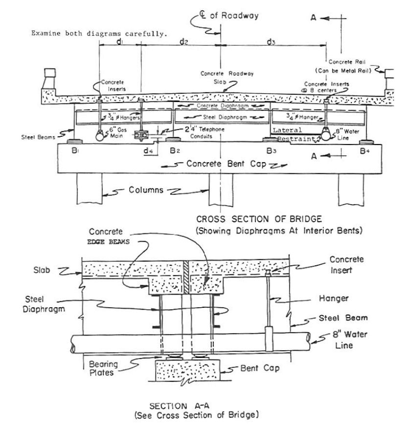
UTILITY ACCOMODATIONS
Often it is necessary for UTILITIES such as water lines, gas lines, telephone lines,
power lines and others to cross the roadway spanned by a bridge. You see in the next
drawing a blown up cross section of a bridge. This is done to show you some parts you
have not seen up to this point and to show how utilities are supported below a bridge
slab.
CHAPTER 9: UTILITIES
Utility plans are used primarily to facilitate coordination between the construction
contractor and utility companies having facilities in the roadway corridor. These plans
show the contractor the approximate locations of existing, relocated, and proposed new
utilities aiding the designer and contractor in identifying and/or avoiding conflicts or
damage to facilities. Information is typically obtained from field survey data and/or the
affected utility owner. A legend, noting utility owners that have facilities on that particular
section of the roadway, is shown on each sheet.
CHAPTER 10: SIGNING AND PAVEMENT MARKINGS, SIGNALS,
HIGHWAY LIGHTING & LANDSCAPING
SIGNS AND PAVEMENT MARKINGS
Plans are also prepared consisting of signs and pavement markings. These plans are
normally in the same general format as the roadway plans.
All permanent roadway signs and pavement markings are placed on the plans as they
are supposed to appear upon completion of the project. See Plan Sheet #9 for an
example of this.
All required pavement markings are depicted on the plans including the color, width,
and spacing, etc. Call-outs may be provided to identify the type of each line on the Plan
Sheet. All required arrows and hatching in accordance with Department Standards are
included. Each arrow may not be labeled but at least one note referencing the appli-
cable standard is usually included on each sheet.
A Tabulation of Signing Quantities usually follows the sign/pavement marking plans.
See Plan Sheet #10 for an example.
TRAFFIC SIGNALS
The signalization plans will show the complete site layout, equipment details, electrical
circuitry, signal phasing, and other relevant data for the installation of traffic signal(s). A
separate plan sheet(s) for each intersection requiring signalization is typically provided.
A summary table of items needed for each intersection will be included showing the
name of the item, the method of payment and the quantity to be used for each of the
installation(s).
LIGHTING
Highway lighting plans are required when a project involves extensive lighting
improvements. The lighting plans are to provide a comprehensive set of construction
details, electrical circuit tabulations, pole data summaries, conduit descriptions, service
point locations, luminaire type and intensity, foundations and details, and all other
specific data relevant to the construction of all lighting related features and components.
LANDSCAPING
The majority of projects which require extensive landscaping will normally have a
separate set of plan sheets for landscaping.
CHAPTER 11: MAINTENANCE OF TRAFFIC, SEQUENCE OF
OPERATIONS AND STAGING
The Traffic Control Plan consists of the plans and specifications developed for each
individual construction project, supplemented by such detailed plans as required by the
contract. The Traffic Control Plan complements the Traffic Control Specifications and
the Manual on Uniform Traffic Control Devices (MUTCD).
Traffic Control Plan sheets for each stage of construction, using information from the
plan sheets and intersection and interchange layout sheets, are prepared for more
complex projects. For each construction stage, plans show the roadway areas and
major drainage structures to be constructed, along with traffic flow patterns, including
lane widths, for the stage. These plan sheets also indicate areas of temporary
pavement, locations of temporary barriers, and any temporary drainage structures.
Also included on these plan sheets is a narrative of the sequence of construction and of
the handling of traffic for each stage. Where necessary, cross sections of the stage
indicating the area to be constructed along with the area to be used to maintain traffic
are included, showing any areas of temporary pavement and any temporary barriers.
There will also be a tabulation of traffic control devices and a tabulation of temporary
striping.
If an on-site detour is required, detour plans with cross sections and signing are usually
included showing detour centerline/baseline with curve and alignment data, detour
profile, pavement edges, pavement width, construction limits of the detour, required
right of way and easements, temporary drainage, and temporary barriers, if necessary.
If a road closing and an off-site detour is required, there will be a plan showing a layout
of the local roads with the road closure points and the detour route.
CHAPTER 12: STORMWATER MANAGEMENT PLAN (SWMP)
All projects involving an earth disturbance require a SWMP. The SWMP is prepared
during the design phase of projects and must be part of the project bid documents.
Projects with one (1) acre or more of earth disturbance require a Colorado Discharge
Permit System (CDPS) permit, which involves the completion and submittal of a
"General Permit for Stormwater Discharges Associated with Construction Activity." The
project plans, and specifications, must define project limits and areas of disturbance,
sequence of construction activity, Best Management Practices (BMPs) for stormwater
pollution prevention, method of material handling and spill prevention, method of waste
disposal, and final stabilization methods. Various erosion control and pollution
prevention requirements must be addressed when developing a SWMP. The main
objective of any SWMP is to prevent sediment from reaching receiving waters. The
SWMP accomplishes this by specifying BMPs for stabilizing earth disturbances and by
including directions for preventing or minimizing erosion associated with construction
activity.
Construction operations must implement the provisions of the SWMP to maintain permit
compliance and avoid incurring regulatory penalties. Although the main objective of the
SWMP is to focus on temporary BMPs used during construction, the SWMP also should
incorporate or reference the permanent water quality measures included in the project.
Permanent BMPs are included in the drainage design of the project; the design process
involves coordination with CDOT environmental specialists, design, construction, and
maintenance personnel. The SWMP must be specific to each project.
The following SWMP site information is required for all projects:
Location map
Discharge locations (applies to projects with drainage plans)
Soil classification
Presence of fisheries, spawning areas, and wetlands
Presence of threatened and endangered species
Area of disturbance
Stream crossings (names of receiving waters)
Unique landscape and cultural values to protect
Identification of existing vegetation
Compliance with Standard Specifications for Water Quality
Key design elements required of all SWMPs are as follows:
Seeding plan to include seeding, mulching, and fertilizing application and
requirements
Requirements to protect existing vegetation
Tabulation and location of erosion and sedimentation control items
Force account erosion control plan to compensate for unforeseen conditions
caused by erosion and sedimentation
Mapping of existing wetlands and wetland mitigation sites
Reference to standard and project specifications pertinent to the SWMP
Reference to drainage features not included in the SWMP
Notes defining methods of implementation of BMPs and plan
Refer to Plan Sheet #11 for an example of a SWMP.
CHAPTER 13: CROSS SECTIONS
Cross sections depict the existing ground conditions, including all man-made features,
as sections perpendicular to the construction centerline or baseline. The proposed cross
sectional outline of the new roadway with all its elements is also shown on the cross
sections.
Standard Cross Section Plan Sheets are used for showing the roadway cross sections.
The recommended scale is 1:100 or 1:200. If the entire cross section cannot be shown
on one sheet, the sheets may be turned horizontally or more sheets with appropriate
match lines shown are used.
Existing ground lines are shown with a dashed line. The surface and subgrade of the
existing construction such as pavements, curbs, and sidewalks are shown also with a
dashed line. The station number of the section is normally shown in heavy numbers to
the right of or below the cross section.
The proposed roadway template is shown with a solid line. The proposed profile grade
elevation is vertically shown just above or below the profile grade line. Station equations
are normally shown, even if a cross section may not be plotted at that point.
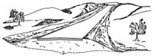
EARTHWORK
Illustrated in the next drawing is a typical terrain upon which a two-lane roadway is
shown. The illustration can only be a general picture, but it does convey a third
dimension-depth, which a plan view cannot show. Within the illustration, you can see
one item of construction that is changing from station to station and that item is
earthwork (cubic yards of dirt).
Because earthwork is usually a costly item in highway construction, it must be
accounted for in the estimate prepared for the project. Since it would be extremely
difficult to measure the exact amount of earthwork in a project, the designer resorts to
approximation. This is accomplished by using the Cross Section Plan Sheets.
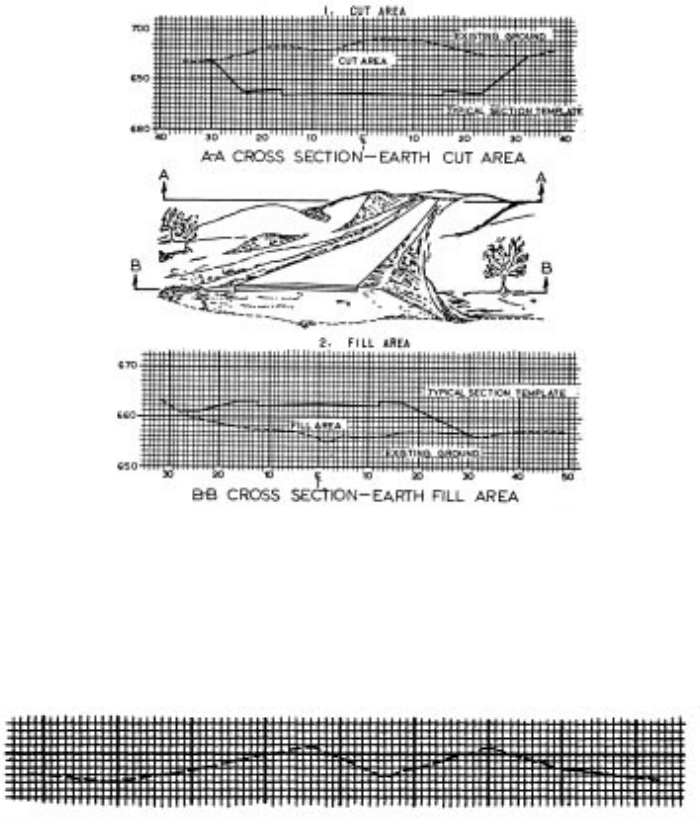
Remember that the cross section shows what you would see if the highway were cut at
right angles to the center line. See the next illustration with examples of cross sections
taken in cut and in fill:
Many factors are considered before combining a typical section of the roadway with a
cross section of the ground. The typical section represents an end view of the pavement
necessary to carry the type and volume of traffic established in the highway design.
The cross section of the original ground is distinctive for every location along the
centerline.
By combining the typical section and the cross section of the original ground, a
determination is made of the area of cut, fill, or both.
The drawing shows how length (100 ft.) is multiplied by an averaging of end areas to
give an earthwork volume between the cross sections. The vertical point of reference for
a typical section at a particular location along the roadway is called the profile grade.
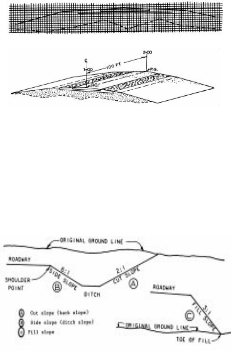
SLOPES
Slopes are usually referred to as cut slopes, fill slopes and side slopes. A cut slope is
that portion of the roadway between the side drainage ditch and the top of the cut. A fill
slope is that portion of roadway between the shoulder point of the roadway and the toe
of the fill. The side slope is that portion of the roadway between the shoulder point and
the adjacent drainage ditch. These slopes are measured as a ratio of horizontal
distance (from and to edge of pavement) versus each foot of decrease or increase in
elevation (height). Next are some views of the various slopes used on cross sections.
A 2:1 slope means that for every 2 feet of horizontal distance, the elevation (or vertical
distance) increases (cut section) or decreases (fill section) 1 foot, depending on the type
of slope shown on the previous drawing.
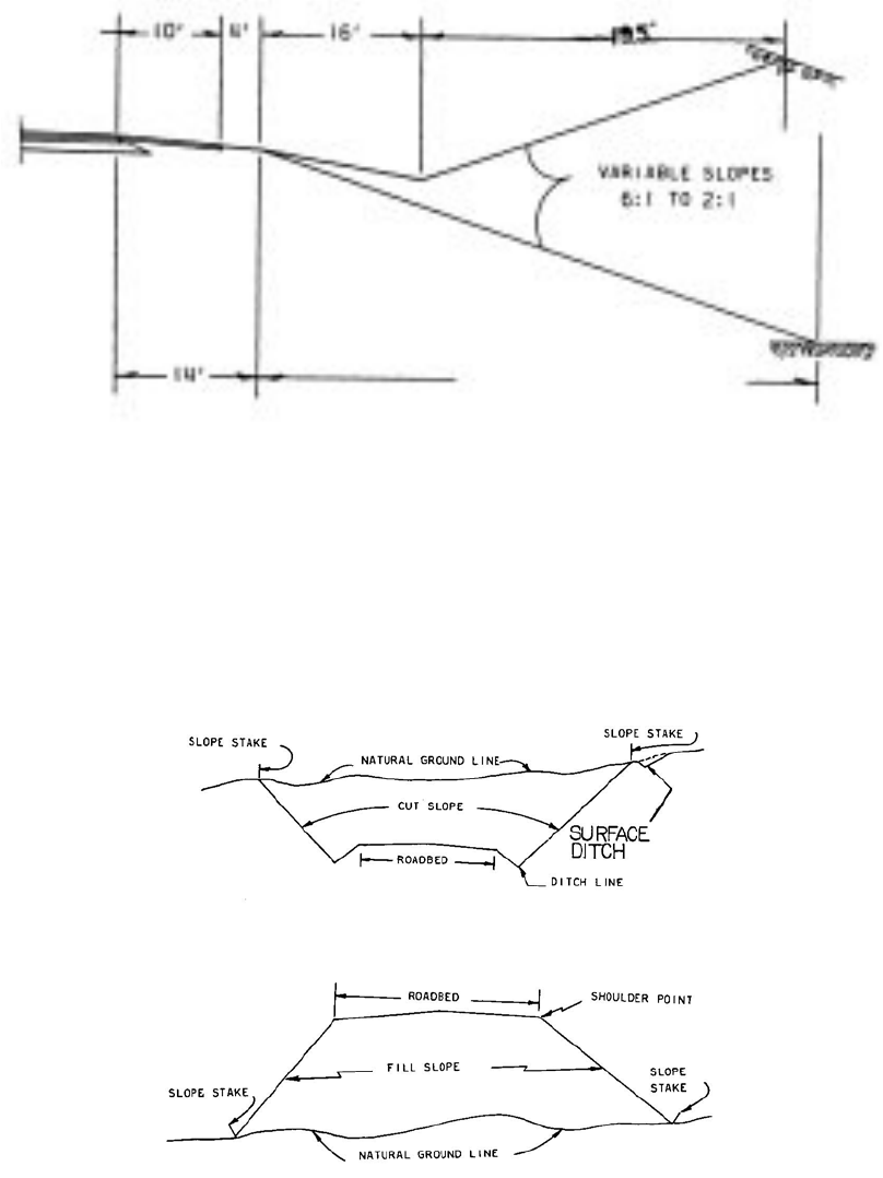
SLOPE STAKES
The following information is a general guide only. Information on these stakes may vary
with various contractors and surveyors. The CDOT Survey Manual has more
information on staking. Stakes contain information that tells the Contractor how much
cut or fill is required from the point of the stake to the ditch line (or shoulder point) of the
roadway, depending on whether the stake is in a cut or in a fill section.
Slope stakes are placed at the point of intersection of the cut or fill slope and the natural
ground line.
The following information may be shown on the side of the slope stake facing the
roadway (this would be the front of the stake):
The amount of cut (to the bottom of the ditch) or the amount of fill (to the shoulder
point).
The distance from the stake to the centerline of the roadway or some other reference
line.
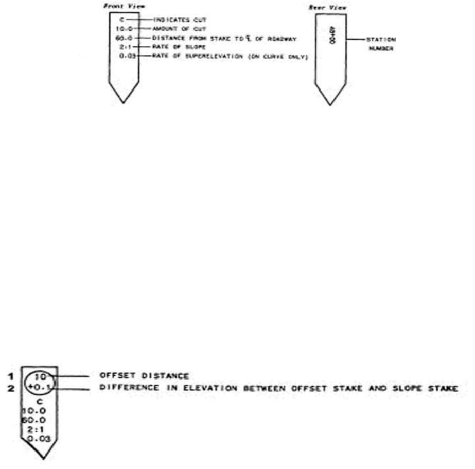
The rate of slope (such as 2:1)
The station number is shown on the side of the stake away from the roadway or back of
the stake. The example shown above includes superelevation information not normally
shown on CDOT slope stakes.
Often, slope stakes are offset in order to allow the Contractor to perform his work
without destroying the slope stakes. In this case, information should be shown in the
same manner as the in-place slope stake except that the following additional
information should be shown encircled on the front of the offset stake:
1. The distance from the offset stake location to the slope stake location.
2. The change in elevation between the slope stake location and the offset location
as indicated by a (+) or a (-) depending on whether the offset stake location is
higher (+) or lower (-)than the slope stake location.
Circle the correct answers:
13-1 Cross sections show what you would see if the highway were cut at a right angle to
the (centerline / station).
13-2 Slope stakes (do/do not) contain information that tells the contractor how much cut
or fill is required for a certain part of the roadway.
Use Plan Sheet #12 to answer the following questions:
13-3 What is the slope of the cut?
13-4 What is the slope of the fill?
13-5 What is the profile grade elevation?
13-6 What is the approximate elevation and offset of the cut slope stake?
CHAPTER 14: STANDARDS AND DETAILS
The M&S Standard Plans are construction drawings that are applicable to most
construction projects. Think of Standards as drawings of the normal way the
Department of Transportation wants something built or to be done. The applicable M&S
standards will be checked on the Standard Plans List. This Standard Plans List is
normally the second plan sheet in a set of plans. See the Standard Plans List in the
M&S Standards.
CHAPTER 15: RIGHT OF WAY
RIGHT OF WAY TERMS AND DEFINITIONS
ACQUISITION OR TAKING - the acquiring of a property in its entirety or a portion
thereof, for highway purposes.
ABUTTING LAND OWNERS - the owners whose land adjoin or abut the land spoken of.
CONDEMNED PROPERTY - power of eminent domain.
DRAINAGE EASEMENT - an instrument or easement granting the Department the
necessary property beyond the right of way limits, as shown on the plans, to provide for
the proper drainage of a highway.
OWNERSHIP - the legal right of possession of real or personal property. Ownership of
property designated on the plans is shown by the owner’s name appearing in print on
the plans.
PARCEL NUMBER - the number designated on the plans, generally enclosed by a
circle, which designates a parcel or tract of land.
PARTIAL TAKE - the acquiring of a portion of a property for highway purposes.
PERMANENT EASEMENT - an easement in perpetuity that gives the Department the
right to utilize property for an unlimited time.
PROPERTY LINE - the boundaries or limits outlining the ownership of a tract or parcel
of land.
RIGHT OF WAY - this is a term denoting land, interest therein, or property which is
acquired for highway purposes.
RIGHT OF WAY BOUNDARY OR LIMITS - the limits or boundaries as shown on the
plans which show how much property is to be acquired for right of way in order to
properly construct the highway.
RIGHT OF WAY MONUMENT - a marker, usually concrete, placed on the ground that
shows or indicates the limits of the right of way.
RIGHT OF WAY PLANS -are plans that contain all necessary information for the
acquisition of right of way as found on design plans with the addition of any additional
information that may be helpful in the acquisition of right of way.
TEMPORARY EASEMENT - an easement granted to the Transportation Department on
a temporary basis for construction usually for a specified time and specified purpose.
RIGHT OF WAY PLAN SHEETS
Right of Way Plans may be a separate set of plans from the construction plans.
Refer to Plan Sheet #13 included with your set of sample plans. You will notice that
there is a list of property owners with corresponding circled numbers. These circled
numbers reference individual parcels and show the location of the property owned by
that person or firm who will be affected by the project.
Notice that Parcel Number 4 belongs to the City and County of Denver Newton Park.
Answers to Chapter Questions
Chapter One:
1 The name of the project 2 The project limits 3 The location map 4 Foxton
Road to Eagle Cliff Road 5 3.50 miles
6 sheets 232-258
Chapter 2:
1 Ten inches 2 Two inches 3 Thirty feet 4 Thirty-eight feet
Chapter 3:
1 AASHTO T180 2 Smoothness category #2 3 Two
Chapter 4:
1 624 square feet 2 227 feet 3 137 feet 4 1733 square yards 5 28 feet
6 Type 3 or Type 5
Chapter 5:
1 Plan, cross section, longitudinal cross section, side elevation, rear elevation.
2 Front 3 Front 4 Back 5 Lead
Chapter 6:
1 100 feet 2 248.6 feet 3 90 feet 4 510 feet 5 412+50 6 411+50 7 a)
549+50 b) 2+50 8 14+00 , 40’ LT.
9 15+25
Chapter 7:
1 False 2 Sta 59+63.65 3 Sta 62+83.65 4 5º15’00” 5 360 degrees 6
Direction 7 N 3º12’38” E 8 vertical alignment 9 centerline 10 feet 11 left
and right 12 Benchmarks 13 +3.290% 14 450 feet
Chapter 8:
1 are 2 over 3 wingwall, headwall, barrel 4 Toewall or curtain wall 5
Horizontal 6 inlet, higher 7 outlet 8 construction joint 9 superstructure,
substructure 10 firm soil, pile 11 concrete, steel 12 reinforced concrete, steel
Chapter 13:
11 centerline 2 do 3 1.5:1 4 2:1 5 8290.23’ 6 8352’, 159’ LT.
