This January 2021 edition supersedes all prior editions
Federal Aviation
Administration
Southern Regional Airports Division
A Quick Reference to
Airfield Standards

A Quick Reference to Airfield Standards Updated January 2021 ii
Airports Division
Table of Contents
Chapter 1 - Airfield Markings .......................................................................................................................... 1
Use of Glass Beads ....................................................................................................................................... 1
Use of Black Borders ..................................................................................................................................... 1
General Guidelines for Painting a Black Border ............................................................................................ 2
Runway Marking Elements ............................................................................................................................ 3
Groupings of Touchdown Zone Markings Required When Installed From One Threshold .......................... 4
Groupings of Touchdown Zone Markings Required When Installed From Both Thresholds ........................ 5
Runway Threshold Stripes for Standard Runway Widths .............................................................................. 6
Runway Marking Dimensions ........................................................................................................................ 7
Precision Instrument .................................................................................................................................. 7
Non-Precision Instrument .......................................................................................................................... 8
Visual ......................................................................................................................................................... 9
Displaced Threshold Markings .................................................................................................................... 10
Taxiway Aligned with a Runway .................................................................................................................. 11
Blast Pad Markings .................................................................................................................................... 12
Aligned Taxiway Preceding a Displaced Threshold ..................................................................................... 13
Blast Pad Preceding a Displaced Threshold ............................................................................................... 14
Enhanced Taxiway Centerline Marking ....................................................................................................... 15
Dashed Lines at Converging Taxiway Centerlines ...................................................................................... 16
Enhanced Taxiway Centerlines Intersecting with Holding Position Marking ............................................... 17
Surface Painted Holding Position Signs for Taxiway Widths Greater Than Thirty Five Feet ..................... 21
Surface Painted Holding Position Sign for Taxiway Widths Equal to or Less Than 35 Feet ...................... 22
Narrow Taxiway Stacked Surface Painted Holding Position Signs ............................................................. 23
Holding Position Marking Details ................................................................................................................. 24
Approach and Departure Sign and Marking Details .................................................................................... 25
Chapter 2 – Airfield Lighting ......................................................................................................................... 26
Sign Element Spacing ................................................................................................................................. 26
Legend and General Notes .......................................................................................................................... 27
Runway Lighting Configuration (HIRL and MIRL Runways) ........................................................................ 28
Runway Lighting Configuration (LIRL Runways and MIRL Visual Runways) .............................................. 29
Threshold / Runway End Lights Installed with LIRLs and MIRLs ................................................................ 30
Threshold / Runway End Lights installed with HIRLs .................................................................................. 31
Runway with a Taxiway at the End .............................................................................................................. 32

A Quick Reference to Airfield Standards Updated January 2021 iii
Airports Division
Runway with a Blast Pad ............................................................................................................................. 33
Lighting for Runway with a Displaced Threshold ......................................................................................... 34
Normal Runway with Taxiway ...................................................................................................................... 35
Lighting for Runway with Displaced Threshold Greater than 700’ ............................................................... 36
Lighting for Runway with Displaced Threshold Less than 700’ .................................................................. 37
Lighting for Runway with Stopway ............................................................................................................... 38
Lighting for Runway with Displaced Threshold and Stopway ...................................................................... 39
Runway with End Taxiway ........................................................................................................................... 40
Lighting for Runway with End Taxiway and Displaced Threshold ............................................................... 41
Color-coding of Exit Taxiway Centerline Lights ........................................................................................... 42
Taxiway Centerline Lighting Configuration for Acute - Angled Exits ............................................................ 43
Typical Layout for Runway End Identifier Lights (REILs) ............................................................................ 44
Chapter 3 – Construction Safety .................................................................................................................. 45
Safety Areas and Work Limits ..................................................................................................................... 45
Construction Reminders .............................................................................................................................. 46
Construction Barricades .............................................................................................................................. 47
Temporary Signs ......................................................................................................................................... 48
Temporarily Closed Runways ...................................................................................................................... 49
Partially Closed Runway .............................................................................................................................. 51
Temporary Partially Closed Runway ........................................................................................................... 53
Temporary Displaced Threshold .................................................................................................................. 54
Lighting Temporarily Relocated or Displaced Runway Thresholds ............................................................. 55
Temporary Taxiway Closure ........................................................................................................................ 57
Chapter 4 - Fuel Fire Safety .......................................................................................................................... 59
Fueling Supervisor and Personnel Training ................................................................................................. 60
Fuel Training Certificates ......................................................................................................................... 60
Sample Fueling Supervisor Training Certificate ....................................................................................... 61
Fueling Inspection – Aircraft Fuel Servicing Vehicles (SAMPLE) ................................................................ 62
Fueling Inspection – Airport Fuel Systems (SAMPLE) ................................................................................ 63
Fueling Inspection – Self-Service Fuel Stations (SAMPLE) ........................................................................ 64
Chapter 5 - Wildlife ........................................................................................................................................ 65
Chapter 6 - Aircraft Rescue and Fire Fighting (ARFF) ............................................................................... 66
ARFF Vehicles ............................................................................................................................................. 66
ARFF Training ............................................................................................................................................. 67

A Quick Reference to Airfield Standards Updated January 2021 iv
Airports Division
Chapter 7 - Pedestrians and Ground Vehicles ............................................................................................ 69
Chapter 8 – References ................................................................................................................................. 70

A Quick Reference to Airfield Standards Updated January 2021 v
Airports Division
PURPOSE
This publication provides a quick reference to several FAA standards as detailed in current FAA Advisory
Circulars (ACs) as of the date of this publication. This guide is not all-inclusive. Consult applicable Aviation
Circulars (ACs) for more details.
Cover photo – Hartsfield-Jackson Atlanta International Airport (ATL)

Chapter 1 - Airfield Markings
A Quick Reference to Airfield Standards Updated January 2021 1
Airports Division
Chapter 1 - Airfield Markings
Reference: AC 150/5340-1
Use of Glass Beads
Where Required Where Recommended
• Runway designation
• Runway and taxiway
centerline
• Threshold markings and bar
• Aiming point marking
• Touchdown zone
• All holding position markings
• Geographic position markings
• Surface painted signs
• Non-movement area boundary
markings
• Runway edge markings
• Taxiway edge markings
• Displaced threshold markings
• Demarcation bar
Note: Never use glass beads in black paint.
Type I beads must be used in the red or pink background paint on SPHPS.
Use of Black Borders
Black borders are required on all “light” colored pavements (including fading asphalt). The table on the next
page has guidelines for determining light-colored pavements.
Where Required Where Recommended
• All holding position marking
• Enhanced Taxiway centerlines
• Non-movement area boundary
markings
• SMGCS Taxiway centerlines
• Surface painted holding signs
• Intermediate holding position
• Geographic position marking
• All runway markings except edge
markings
• Runway edge markings
• Runway demarcation bar
• Taxiway centerlines
• Taxiway edge markings
• Chevrons
• Shoulder markings
Chapter 1 - Airfield Markings
A Quick Reference to Airfield Standards Updated January 2021 2
Airports Division
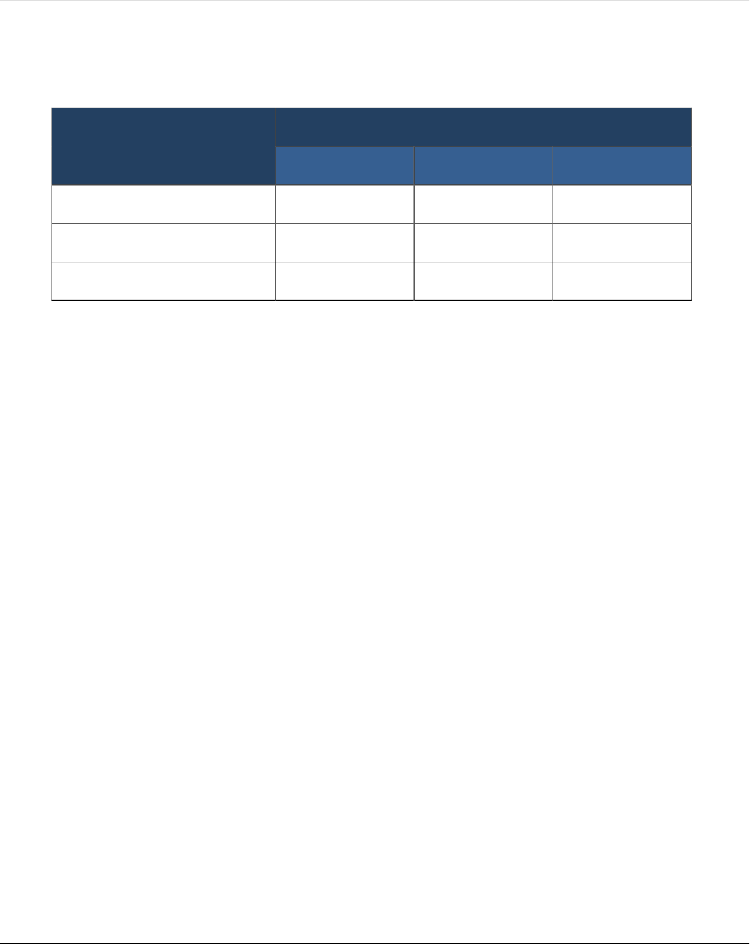
General Guidelines for Painting a Black Border
Paint a Black Border
Pavement Surface Type
Age of Pavement Surfaces
New Up to 2 years old Over 2 years old
Portland Cement Concrete Yes Yes Yes
Asphalt Concrete No No Yes
Asphalt Treated No No Yes
This table serves only as a general guide. An existing asphalt pavement at one airport location may not
experience the same rate of surface color deterioration as at another airport location.
Chapter 1 - Airfield Markings
A Quick Reference to Airfield Standards Updated January 2021 3
Airports Division
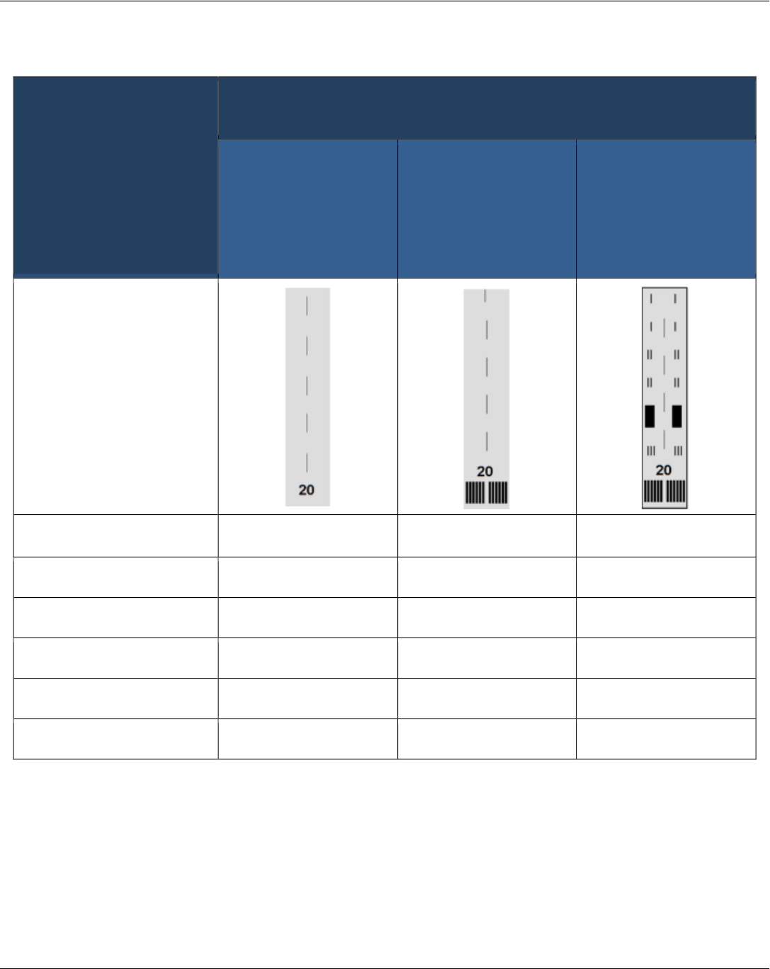
Runway Marking Elements
Notes:
1. Required on runways serving approach categories C and D airplanes and for runways used, or
intended to be used by international commercial air transport.
2. Required on 4,200 foot or longer runways serving approach categories C and D airplanes.
3. Required on 4,200 foot or longer instrumented runways.
4. Used when the full runway pavement width may not be available for use as a runway.
Runway Surface Marking
Scheme
Threshold Approach Category
Visual Approach
Non-precision
Approach
(Approaches with
vertical guidance not
lower than 0.75
statute mile visibility)
Precision Approach
(Approaches with
vertical guidance
lower than 0.75
statute mile visibility)
Runway diagram
Landing Designator
Required Required Required
Centerline
Required Required Required
Threshold
Note 1 Required Required
Aiming Point
Note 2 Note 3 Required
Touchdown Zone
(not applicable) (not applicable) Required
Edge Markings
Note 4 Note 4 Required

Chapter 1 - Airfield Markings
A Quick Reference to Airfield Standards Updated January 2021 4
Airports Division
Groupings of Touchdown Zone Markings
Required When Installed From One Threshold
Distance Between Thresholds
(or displaced thresholds) (feet)
Markings for Precision
Approach End (includes
displaced threshold)
Other Runway End,
Visual or Non-precision
6,065 or greater
(Note 1)
Full set of markings Aiming point markings
5,565 - 6,064
Less one grouping of rectangular
bar markings (Note 2)
Aiming point marking
5,065 - 5,564
Less two groupings of rectangular
bar markings
Aiming point marking
4,565 - 5,064
Less three groupings of
rectangular bar markings
Aiming point marking
Notes:
1. Derive the value of 6,065 feet as follows:
a. For the non-precision or visual runway end, the table assumes the 900 foot “no marking zone”
criterion plus the length of a preferred aiming point marking, which starts 1,020 feet from the
start of the threshold to obtain a length of 1,920 feet.
b. Add to this the length of the aiming point marking. The length of the aiming point marking is
either 150 or 100 feet. This table uses a length of 150 feet because all the entries in column 1
are greater than 4,200 feet. Therefore, adding 150 feet to 1,920 feet obtains a length of 2,070
feet. For the precision end, which equals 3,995 feet, it assumes the 900 foot “no marking zone”
followed by the standard 75-foot long rectangular bar for a total length of 975 feet.
c. Add to this value the full 3,000-foot touchdown zone marking scheme and the 20-foot
separation between the actual starting point of the runway threshold (or displaced threshold)
and the bottom edge of the threshold marking to obtain 3,995 feet.
d. Summing the values 3,995 and 2,070 yields 6,065 feet.
2. Each reduction in a pair of rectangular bar markings from the precision end equates to a 500-foot
reduction between the thresholds.
The painting rationale for this table is to ignore the midpoint between the thresholds so the precision-
instrumented landing is favored over non-precision or visual landings.
The length of the non-precision or visual side of the runways always remains at 2,070 feet in length to promote
the painting a full set of touchdown zone markings.

Chapter 1 - Airfield Markings
A Quick Reference to Airfield Standards Updated January 2021 5
Airports Division
Groupings of Touchdown Zone Markings
Required When Installed From Both Thresholds
Distance Between Thresholds
(or displaced thresholds) (feet)
Markings for Each Threshold
(or displaced threshold)
7,990 or greater (Note 1) Full set of markings
6,990 - 7989
Less one grouping of rectangular bars from each
side nearest to the runway midpoint (Note 2)
5,990 - 6,989
Less two groupings of rectangular bars from each
side nearest to the runway midpoint (Note 2)
4,990 - 5,989
Less three groupings of rectangular bars from each
side nearest to the runway midpoint (Note 2)
Notes:
1. The value of 7,990 feet is derived as follows:
a. Proceed from the runway midpoint in one direction and you will have the 900-foot “no marking
zone” criterion followed by the standard 75-foot long rectangular bar for a total length of 975
feet.
b. Add to this value the full 3000-foot touchdown zone marking scheme plus the 20-foot
separation between the actual starting point of the runway threshold (or displaced threshold)
and the edge of the threshold marking to obtain 3,995 feet.
c. Double this value for both directions to obtain 7,990 feet.
2. Each reduction in a pair of rectangular bar markings from both sides equates to a 1,000-foot reduction
between the thresholds.
The painting rationale for this table is to preserve the midpoint between the thresholds, thereby promoting an
equal treatment of painting pairs of rectangular bar markings for both sides.
Chapter 1 - Airfield Markings
A Quick Reference to Airfield Standards Updated January 2021 6
Airports Division
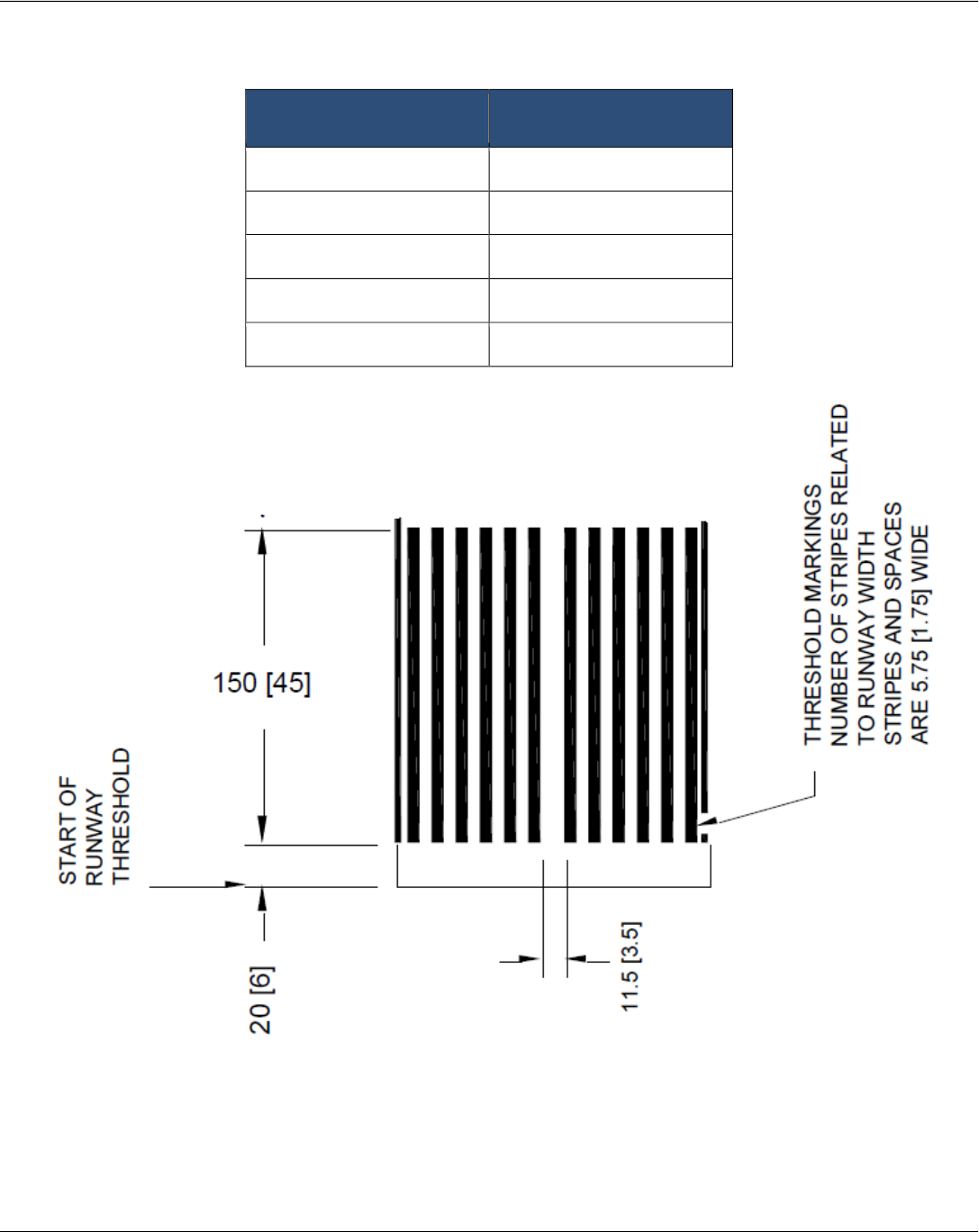
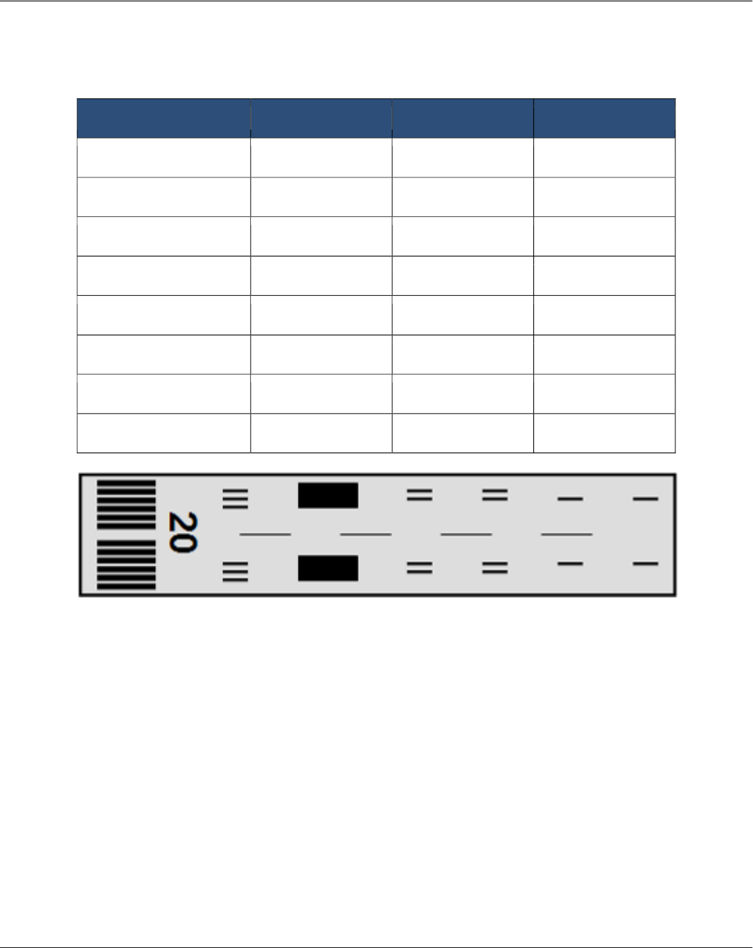
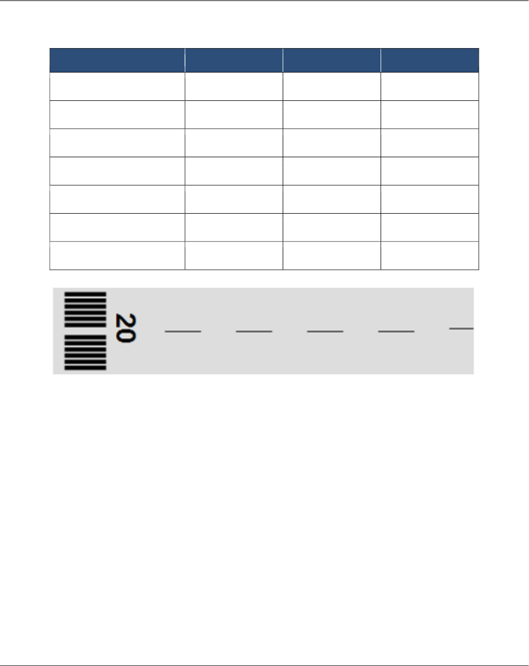
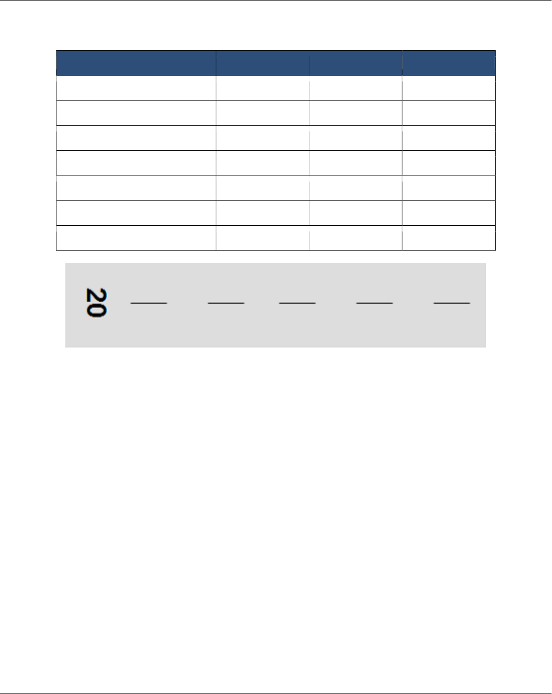
Runway Threshold Stripes for Standard Runway Widths
Runway width Number of stripes
60 feet
4
75 feet
6
100 feet
8
150 feet
12
200 feet
16
150-foot-wide runway
Chapter 1 - Airfield Markings
A Quick Reference to Airfield Standards Updated January 2021 7
Airports Division
Runway Marking Dimensions
Precision Instrument
Runway marking 100’ Wide 150’ Wide 200’ Wide
Designation
60’L 60’L 60’L
Centerline (note 1) 120’Lx36”W 120’Lx36”W 120’Lx36”W
Edge
36” wide 36” wide 36” wide
Threshold Bar
10’ wide 10’ wide 10’ wide
Threshold Markings
150’Lx5.75’W 150’Lx5.75’W 150’Lx5.75’W
Aiming Point (note 2) 150’Lx20’W 150’Lx30’W 150’Lx30’W
Touchdown Zone
75’Lx4’W 75’Lx6’W 75’Lx6’W
Demarcation (note 3) 3’ wide 3’ wide 3’ wide
Notes:
1. Gaps are 80 feet in length. Adjust the length of the stripes and gaps near the runway midpoint where
necessary to accommodate the runway length.
2. Aiming Point markings may be reduced to 100 feet in length for runways under 4200 feet in length
between the thresholds or a displaced threshold(s).
3. A demarcation bar delineates a runway with a displaced threshold from a blast pad, stopway, or
taxiway that precedes the runway and is not usable pavement. A demarcation bar is yellow in color.
Chapter 1 - Airfield Markings
A Quick Reference to Airfield Standards Updated January 2021 8
Airports Division
Non-Precision Instrument
Runway marking 100’ Wide 150’ Wide 200’ Wide
Designation
60’L 60’L 60’L
Centerline (note 1) 120’Lx18”W 120’Lx18”W 120’Lx18”W
Edge (optional) (note 2) 36” wide 36” wide 36” wide
Threshold Bar
10’ wide 10’ wide 10’ wide
Threshold Markings
150’Lx5.75’W 150’Lx5.75’W 150’Lx5.75’W
Aiming Point (note 3) 150’Lx20’W 150’Lx30’W 150’Lx30’W
Demarcation (note 4) 3’ wide 3’ wide 3’ wide
Notes:
1. Gaps are 80 feet in length. Adjust the length of the stripes and gaps near the runway midpoint where
necessary to accommodate the runway length.
2. Used when the full pavement width may not be available as a runway.
3. Required on 4,200 feet or longer instrumented runways. Note: Aiming Point markings may be reduced
to 100 feet in length for runways under 4200 feet in length between the thresholds or a displaced
threshold(s).
4. A demarcation bar delineates a runway with a displaced threshold from a blast pad, stopway, or
taxiway that precedes the runway and is not usable pavement. A demarcation bar is yellow in color.
Chapter 1 - Airfield Markings
A Quick Reference to Airfield Standards Updated January 2021 9
Airports Division
Visual
Runway 100’ Wide 150’ Wide 200’ Wide
Designation
60’L 60’L 60’L
Centerline (note 1) 120’Lx12”W 120’Lx12”W 120’Lx12”W
Edge (optional) (note 2) 36” wide 36” wide 36” wide
Threshold Bar
10’ wide 10’ wide 10’ wide
Threshold Markings (note 3) 150’Lx5.75’W 150’Lx5.75’W 150’Lx5.75’W
Aiming Point (note 4) 150’Lx20’W 150’Lx30’W 150’Lx30’W
Demarcation (note 5) 3’ wide 3’ wide 3’ wide
Notes:
1. Gaps are 80 feet in length. Adjust the length of the stripes and gaps near the runway midpoint where
necessary to accommodate the runway length.
2. Used when the full pavement width may not be available as a runway.
3. Required on runways serving approach category C and D airplanes or on runways used by
international commercial transport.
4. Required on runways 4,200 feet or longer used by approach category C and D aircraft. Note: Aiming
Point markings may be reduced to 100 feet in length for runways under 4200 feet in length between the
thresholds or a displaced threshold(s).
5. A demarcation bar delineates a runway with a displaced threshold from a blast pad, stopway, or
taxiway that precedes the runway and is not usable pavement. A demarcation bar is yellow in color.
Chapter 1 - Airfield Markings
A Quick Reference to Airfield Standards Updated January 2021 10
Airports Division
Displaced Threshold Markings
Chapter 1 - Airfield Markings
A Quick Reference to Airfield Standards Updated January 2021 11
Airports Division
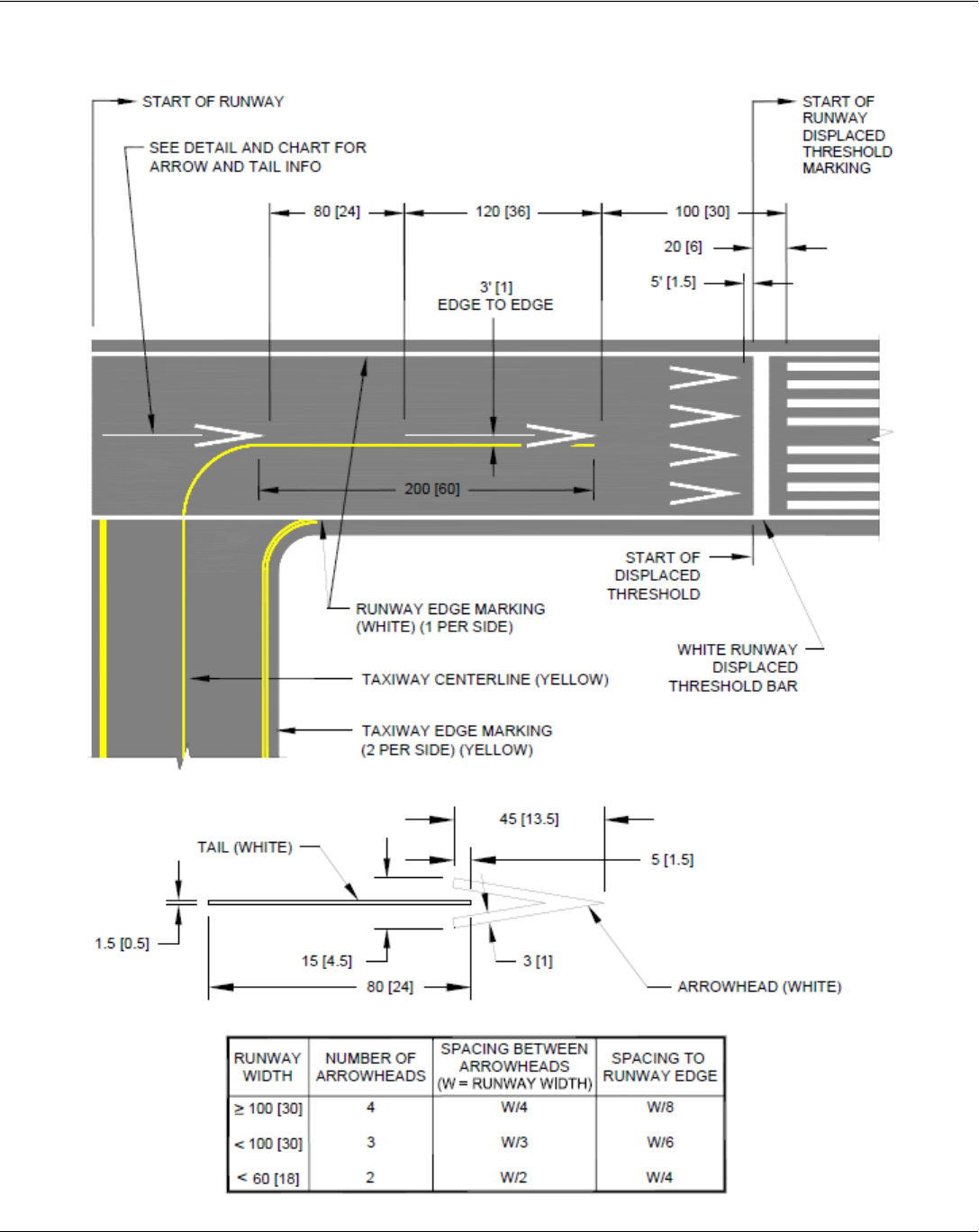
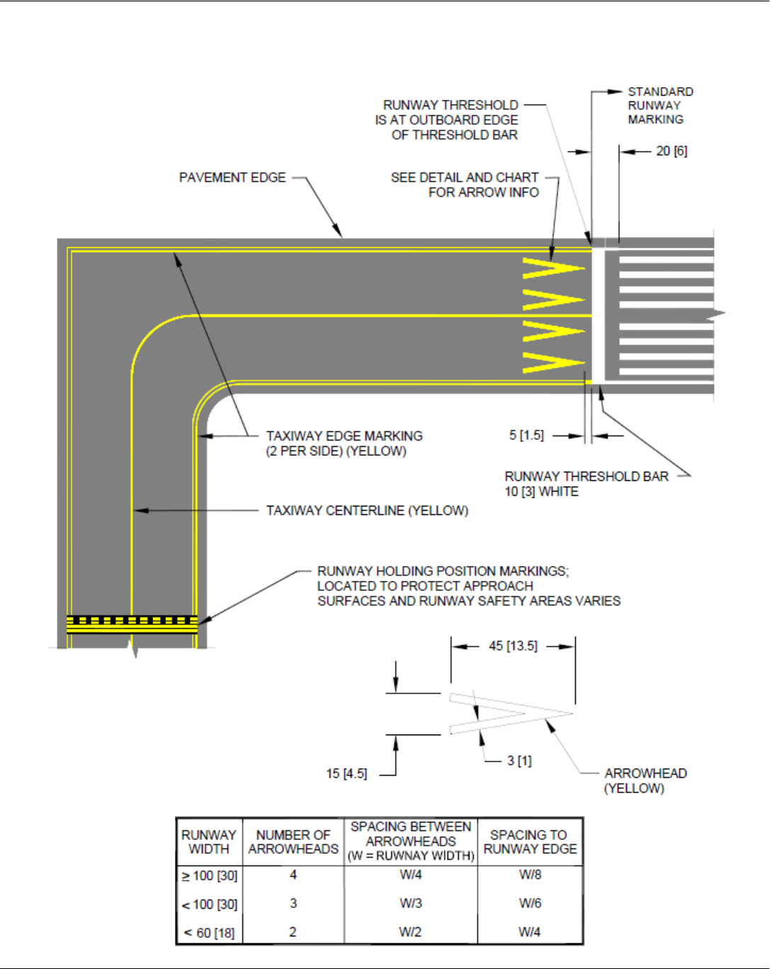
Taxiway Aligned with a Runway
Chapter 1 - Airfield Markings
A Quick Reference to Airfield Standards Updated January 2021 12
Airports Division
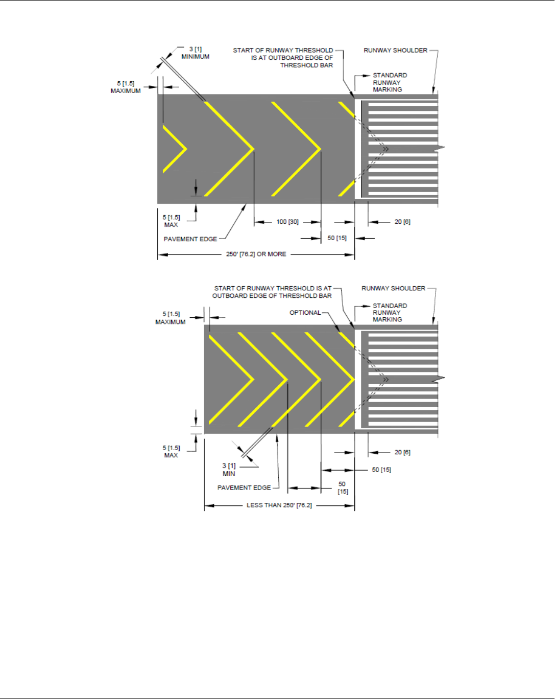
Blast Pad Markings
Notes:
• The image shows dimensions in feet, with meters following in parentheses.
• The widths of the stopways and blast pads are not the same. Stopways equal runway width. Blast
pads equal runway width plus runway shoulders.
• 50-foot spacing may be used when length of area is less than 250 feet in which case the first full
chevron starts at the index point (intersection of runway centerline and runway threshold).
• Chevrons are painted yellow and at an angle of 45 degrees to the runway centerline.
• Chevron spacing may be doubled if length of area exceeds 1000 feet.
• For stopways of less than 250 feet in length, full chevrons are required with the option to paint
partial chevrons
Chapter 1 - Airfield Markings
A Quick Reference to Airfield Standards Updated January 2021 13
Airports Division
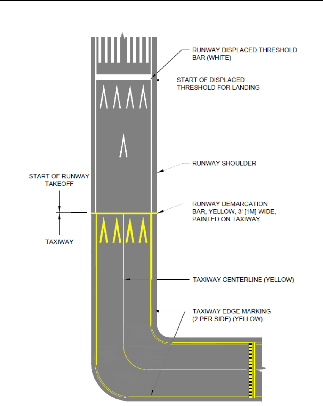
Aligned Taxiway Preceding a Displaced Threshold
Chapter 1 - Airfield Markings
A Quick Reference to Airfield Standards Updated January 2021 14
Airports Division
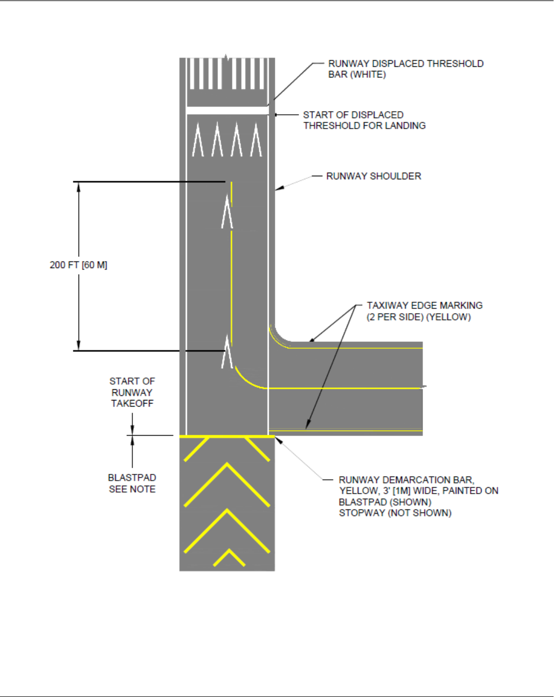
Blast Pad Preceding a Displaced Threshold
Note: Demarcation bars are 3 feet wide and not part of the useable pavement. Stopway width
equals runway width. Blast pad width equals runway width plus runway shoulders.
Chapter 1 - Airfield Markings
A Quick Reference to Airfield Standards Updated January 2021 15
Airports Division
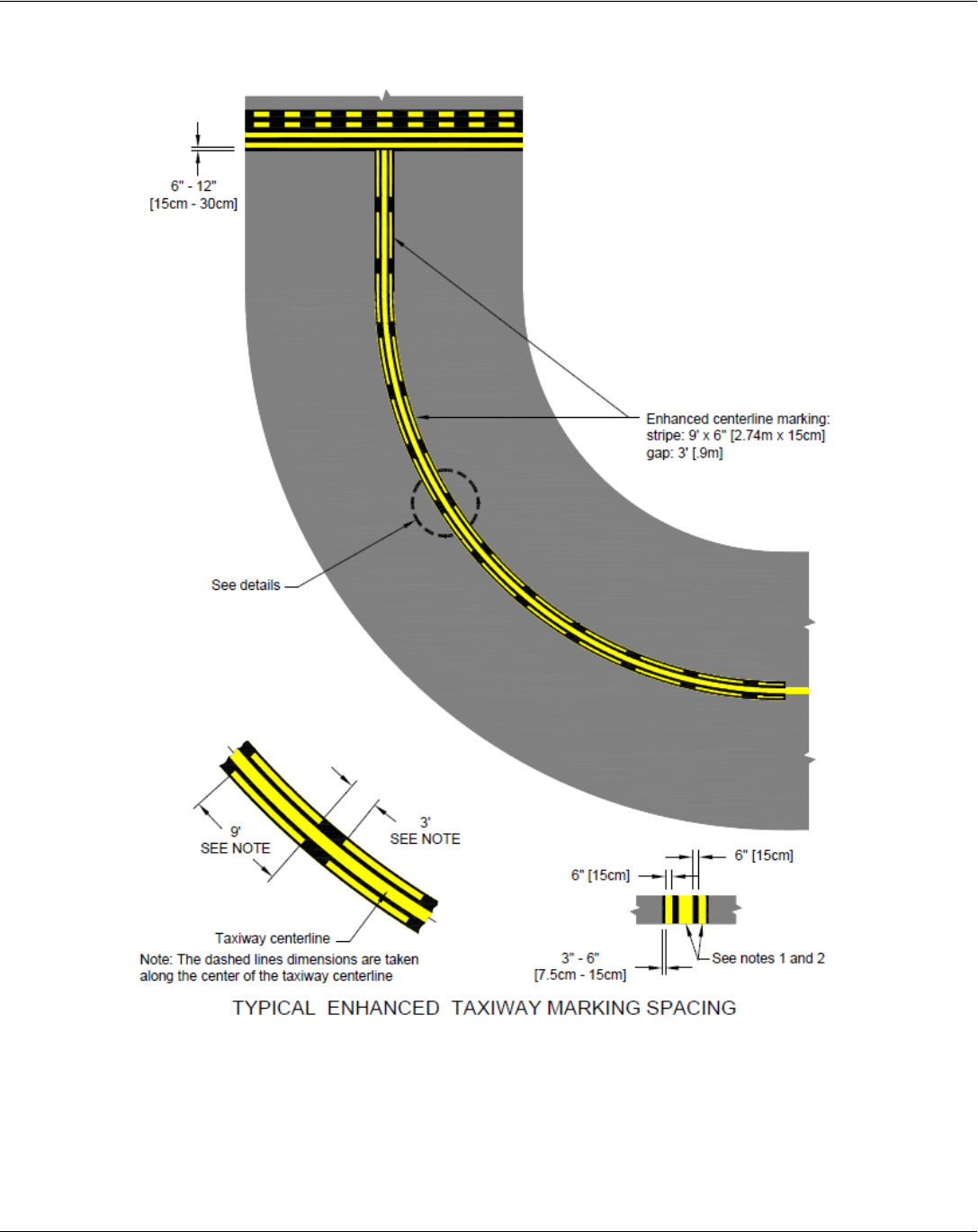
Enhanced Taxiway Centerline Marking
Notes:
• Dashed lines for the enhanced taxiway centerline marking are 6 inches in width and separated by 6
inches from the taxiway centerline. This applies to both 6 inch and 12-inch taxiway centerline markings
• The taxiway centerline markings may be shifted left or right to avoid interference with the taxiway
centerline lights or lights and their housing can be covered up temporarily during the painting process.
Chapter 1 - Airfield Markings
A Quick Reference to Airfield Standards Updated January 2021 16
Airports Division
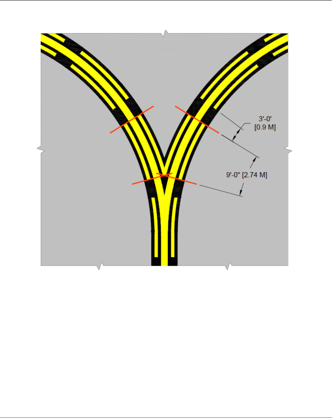
Dashed Lines at Converging Taxiway Centerlines
Notes:
• As shown in this case, the V-shaped inner dashes start and stop with the outside 9-foot dashes.
However, this may not always be the case for the inner dashes. If the V-shaped are less than 5 feet,
they may be omitted.
• Measure along the center of the centerline stripe.
Chapter 1 - Airfield Markings
A Quick Reference to Airfield Standards Updated January 2021 17
Airports Division
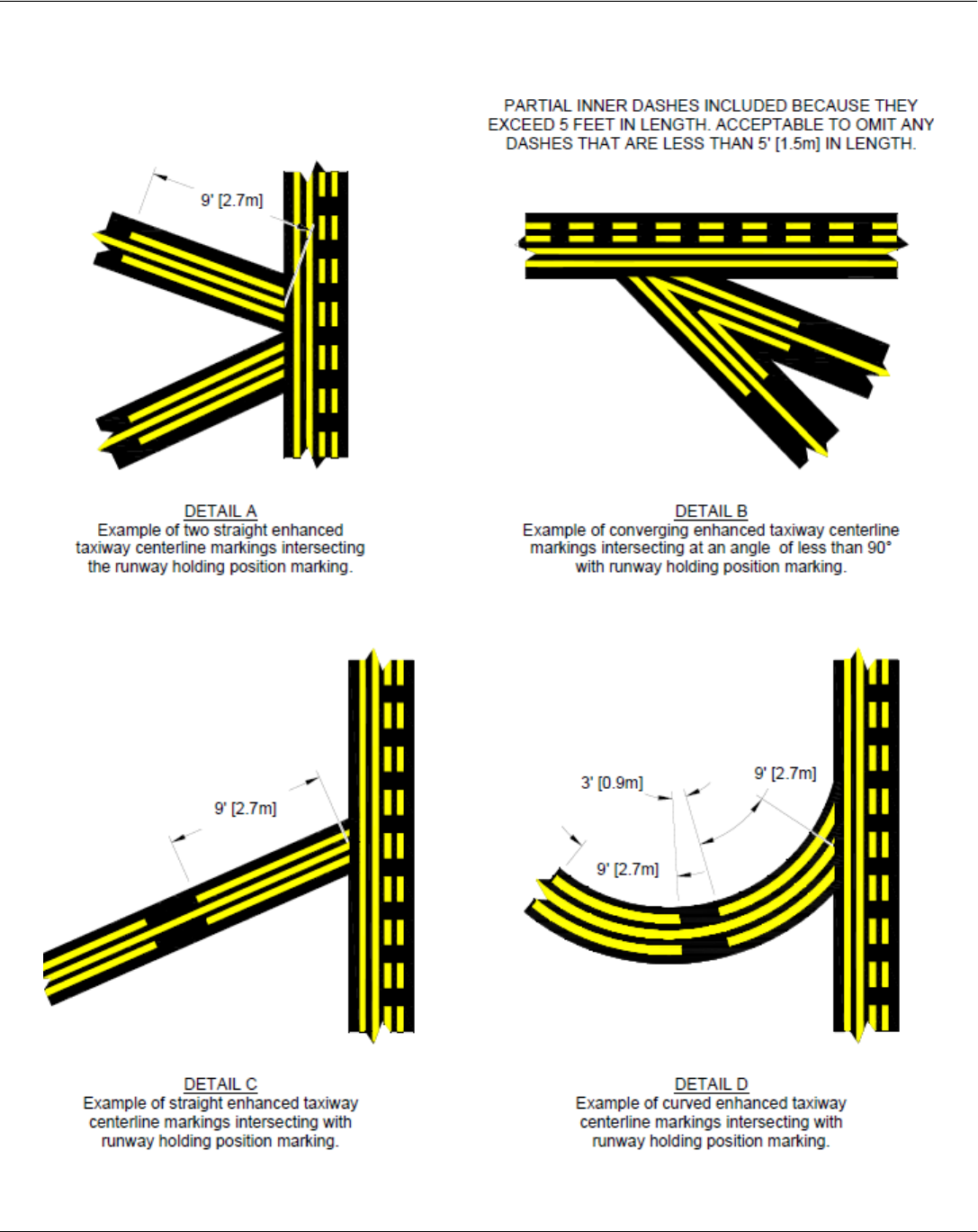
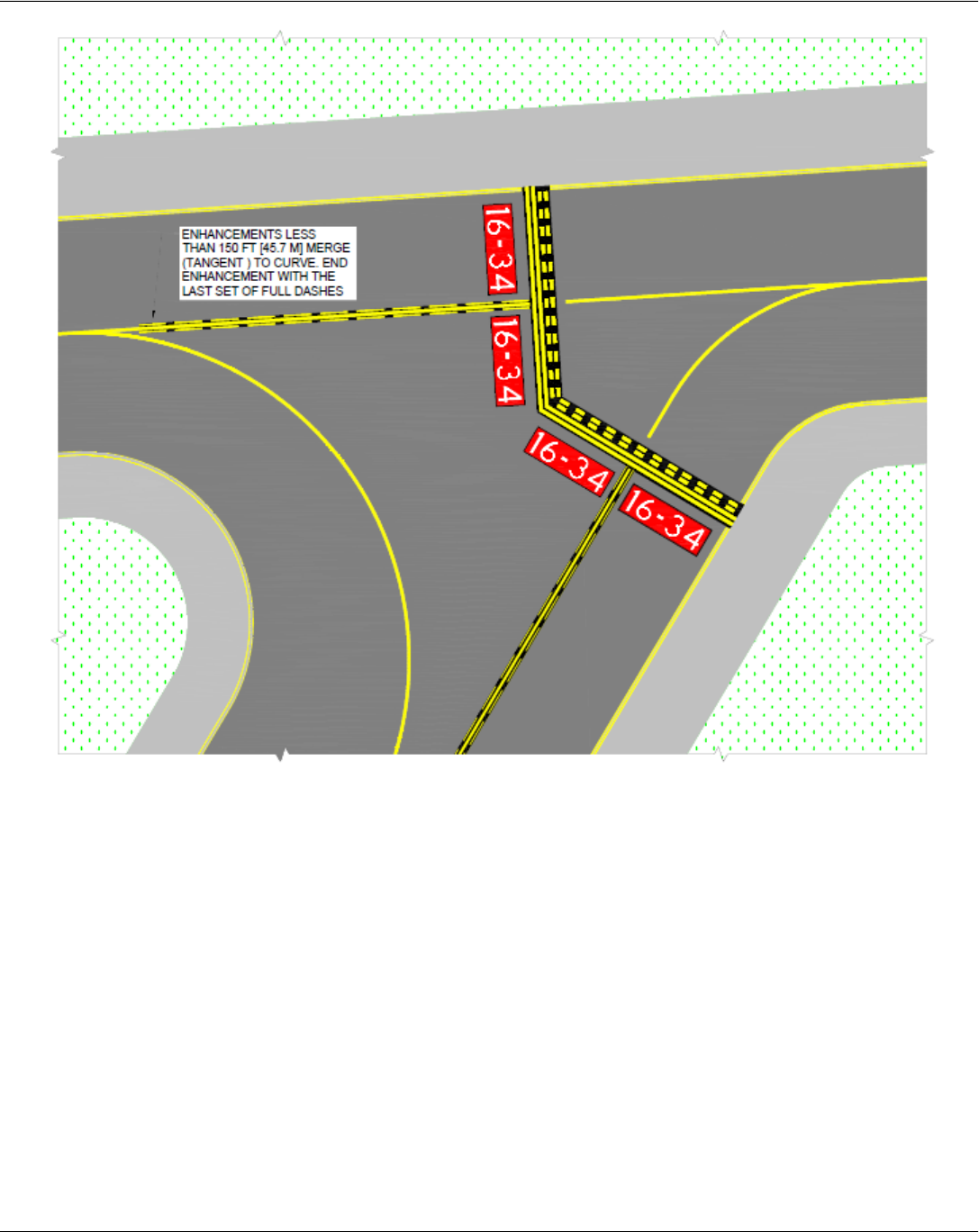
Enhanced Taxiway Centerlines Intersecting with Holding Position Marking
Note: All measurements are taken along the center of the centerline.
Chapter 1 - Airfield Markings
A Quick Reference to Airfield Standards Updated January 2021 18
Airports Division
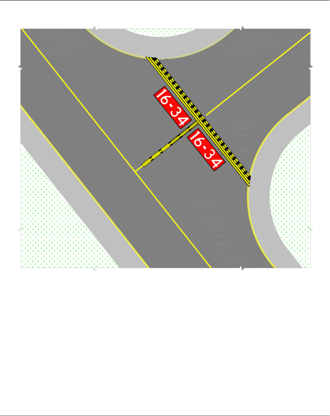
Notes:
1. Enhancement is tangent to merging curve.
2. Enhancement terminates 5 feet (1.5 m) from intersection.
Chapter 1 - Airfield Markings
A Quick Reference to Airfield Standards Updated January 2021 19
Airports Division
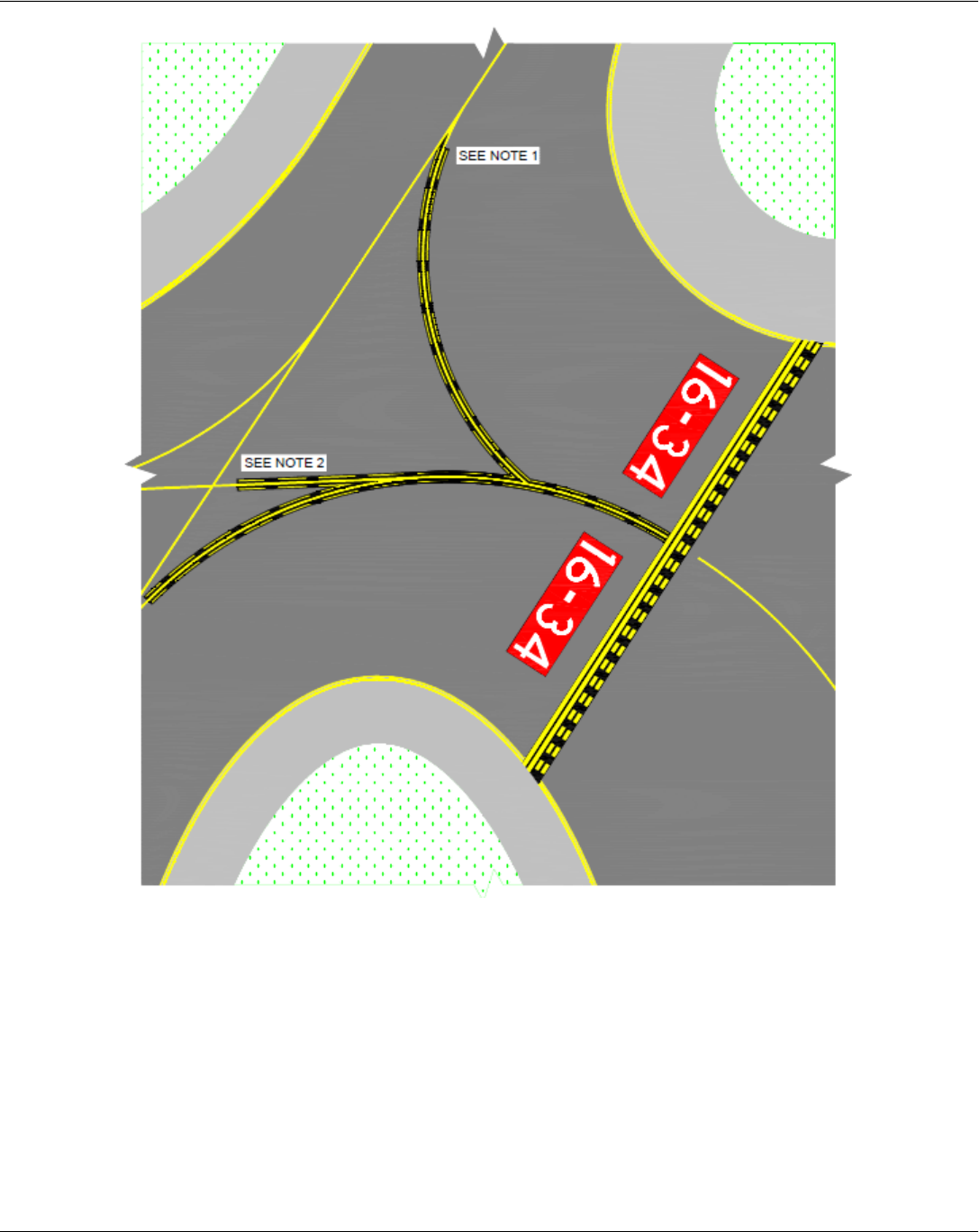
Notes:
• Enhancements less than 150 feet merge (tangent) to the curve
• End enhancement with the last set of full dashes
Chapter 1 - Airfield Markings
A Quick Reference to Airfield Standards Updated January 2021 20
Airports Division
Note: The enhancement terminates 5 feet from the taxiway/taxiway intersection.
Chapter 1 - Airfield Markings
A Quick Reference to Airfield Standards Updated January 2021 21
Airports Division
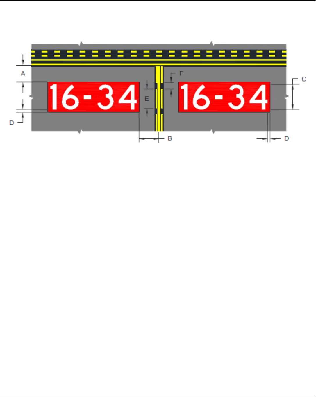
Surface Painted Holding Position Signs for Taxiway Widths
Greater Than Thirty Five Feet
Notes: Dimensions:
A = 2 to 4 feet
B = 3 to 10 feet
C = 9 to 12 feet
Inscriptions must have a height of 12 feet; however, the height may be reduced as necessary, to
the minimum height of 9 feet. In special situations, the surface painted marking may be reduced
to less than 9 feet in order to fit the marking appropriately. Examples of special situations
include taxiways with widths narrower than 75 feet or taiways tha need to display multiple
runway designations with arrows. In all cases, inscriptions follow the Advisory Circular,
Appendix A, inscription criteria. All other taxiway entrances to the same runway not needing the
reduction are to maintain the 12 foot height dimension. For practicality, the lowest height
reduction is 6 feet. In all cases the dimension D is not reduced.
D = 15 inches
E = 9 feet
F = 3 feet
Chapter 1 - Airfield Markings
A Quick Reference to Airfield Standards Updated January 2021 22
Airports Division
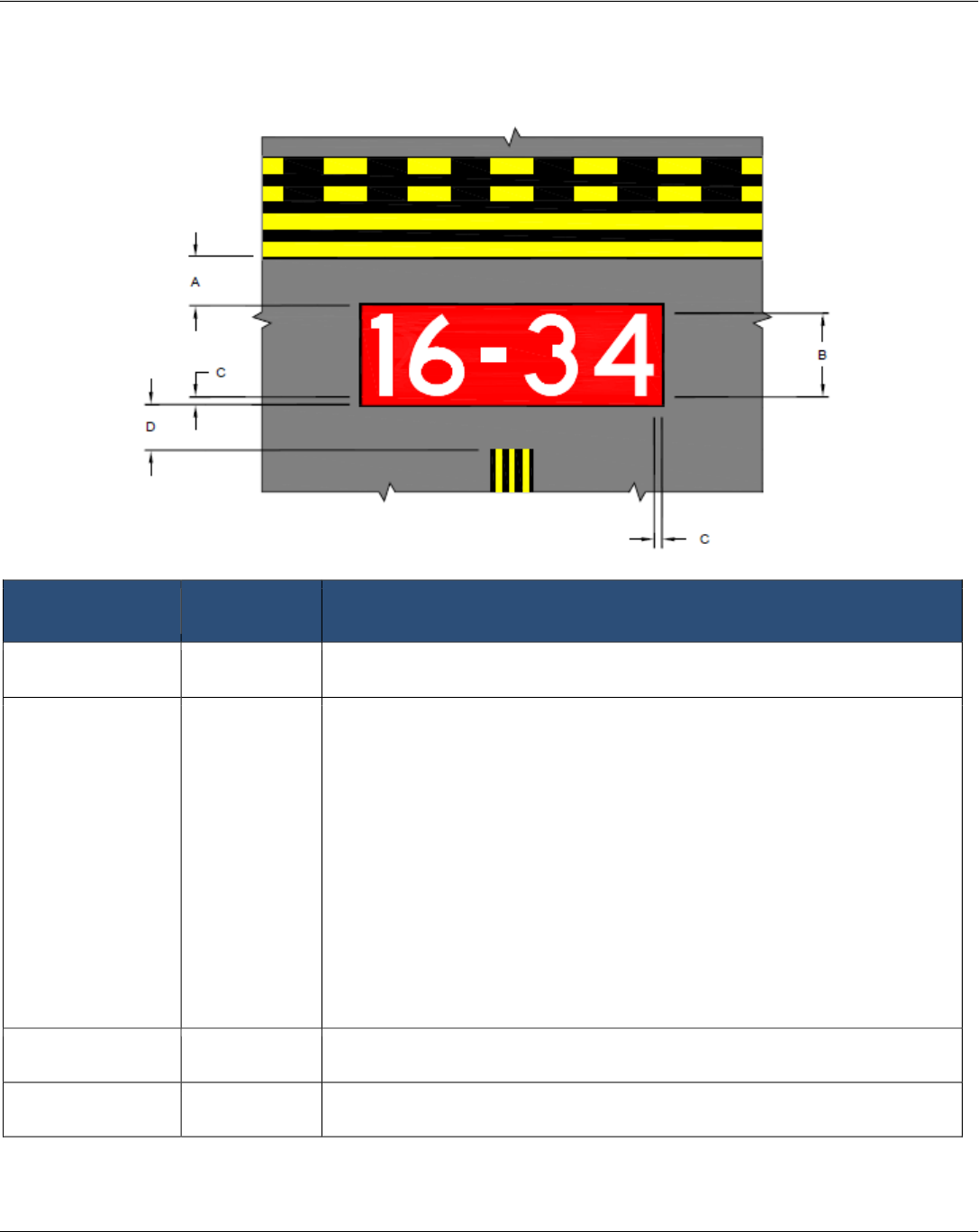
Surface Painted Holding Position Sign for Taxiway Widths
Equal to or Less Than 35 Feet
Dimension letter
(in image above)
Dimension Notes
A
2-3 feet (none)
B
6 feet Inscriptions follow the Advisory Circular, Appendix A, inscription
criteria. The size of the sign inscription is scaled to fit taxiways 35 feet
or less in width for Airplane Design Group I and II. Reference AC
150/5300-13.
In special situations the surface marking may be reduced to less than
6 feet in order to fit the marking appropriately. Examples of special
situations include taxiways that need to display multiple runway
designations with arrows. In all cases, the inscriptions follow the
Advisory Circular, Appendix A, inscription criteria. All other taxiway
entrances to the same runway not needing the reduction are to
maintain the 6-foot height dimension.
For practicality, the lowest height reduction is 3 feet.
C
7.5 inches (none)
D
36 inches The dimensions for the enhanced taxiway centerline are in Figure D-1.
Note: The dimensions for the enhanced taxiway centerline are in Figure D-1 of the Advisory Circular.
Chapter 1 - Airfield Markings
A Quick Reference to Airfield Standards Updated January 2021 23
Airports Division
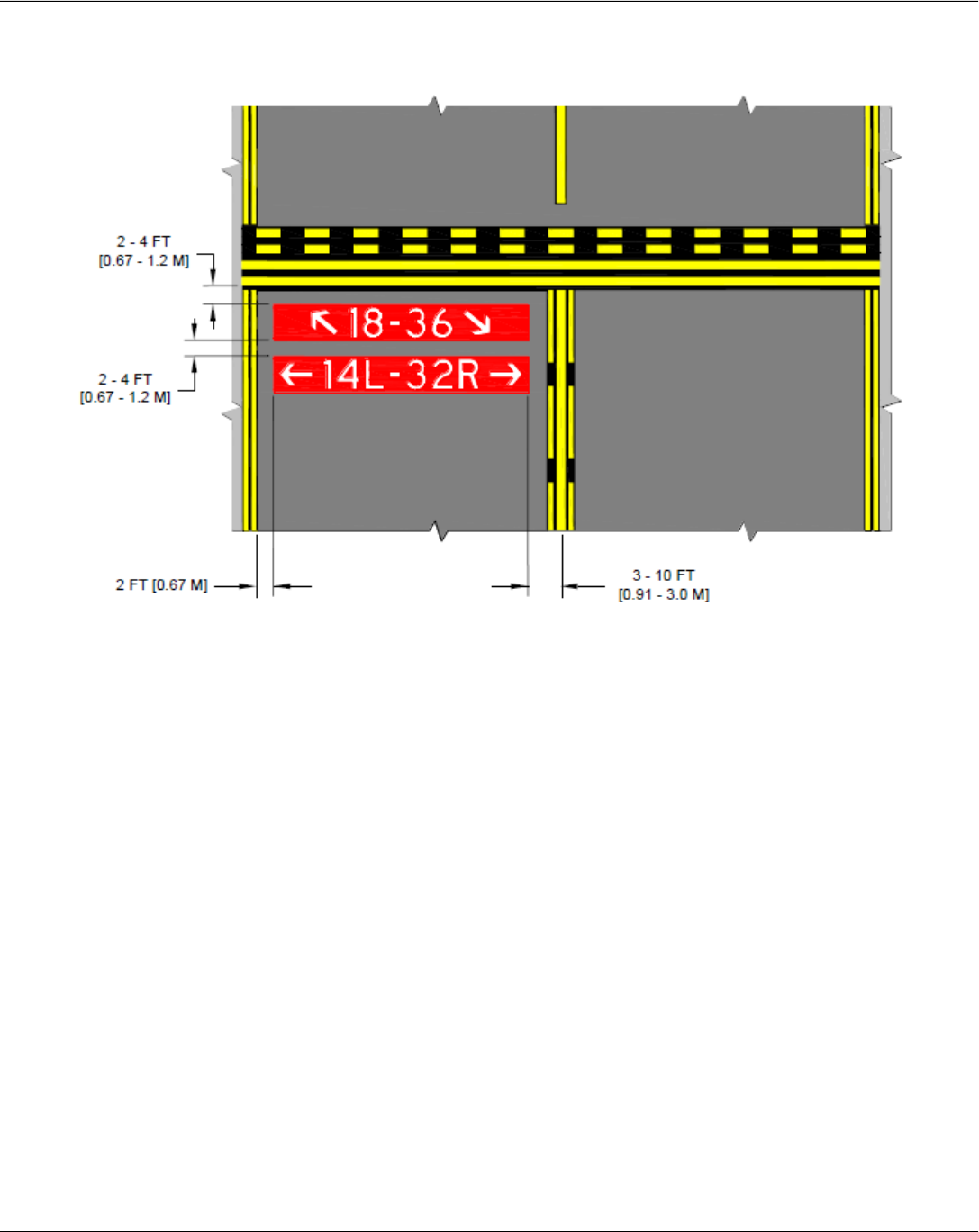
Narrow Taxiway Stacked Surface Painted Holding Position Signs
Notes:
1. Stacked surface painted holding position signs for narrow taxiways.
2. The recommended order of appearance is as follows:
a. If the “stacked” surface painted holding position signs are for a taxiway that clearly accesses
one runway (for example, Runway 14L-32R) before another runway (Runway 18-36), then the
order of appearance is from “bottom up” as shown above.
b. If the “stacked” surface painted holding position signs are for a taxiway that equally offers
access to two or more runways, then follow a “clockwise” order of appearance as viewed for the
holding position. Hence, the bottorm surface painted holding position sign is the first runway as
viewed from the holding position. This practice follows the signage convention.
3. For taxiways less than or equal to 35 feet wide, the stacked surface painted signs are located centered
on the taxiway in accordance with the figure ont he previous page.

Chapter 1 - Airfield Markings
A Quick Reference to Airfield Standards Updated January 2021 24
Airports Division
Holding Position Marking Details
Chapter 1 - Airfield Markings
A Quick Reference to Airfield Standards Updated January 2021 25
Airports Division
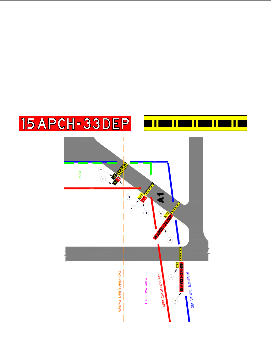
Approach and Departure Sign and Marking Details
Reference: AC 150/5340-18
1.5.4 Holding Position Sign for Runway Approach/Departure Areas.
The inscription on a sign for a runway approach/departure area is the associated and complete runway designation
followed by a dash and the abbreviation “## APCH-## DEP”. The sign is installed on taxiways located in
approach/departure areas where an aircraft on a taxiway would either enter or penetrate the airspace required for the
approach or departure runway (including clearway). This holding position sign is installed in-line with the associated
painted marking.
Note 1: Consult with local air traffic personnel to ensure awareness of holding position signs.
Note 2: The approach/hold sign may be installed on a runway for purpose such as snow removal operator’s
situational awareness.
Chapter 2 - Airfield Lighting
A Quick Reference to Airfield Standards Updated January 2021 26
Airports Division
Chapter 2 – Airfield Lighting
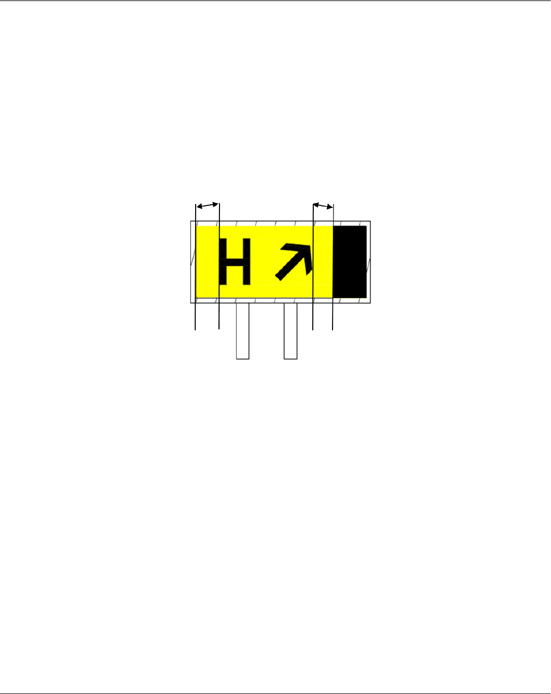
Sign Element Spacing
Reference: AC 150/5345-44
3.2.5.2 Lighted Sign Sizes
The horizontal spacing/separation distance between message elements in a sign array within a common
continuous housing must be between at least 3 inches (76 mm) and must not exceed 12 inches (305mm) for a
Size 1, 14 inches (356 mm) for a Size 2 and 16 inches (406 mm) for a Size 3 sign.
If the sign panel viewable horizontal length exceeds the maximum spacing allowable for the message
elements, then the overage on the panel must be blanked out (black) at the outboard end of the legend in
relation to its mounting (left or right side) adjacent to the Taxiway/Runway.
Chapter 2 - Airfield Lighting
A Quick Reference to Airfield Standards Updated January 2021 27
Airports Division
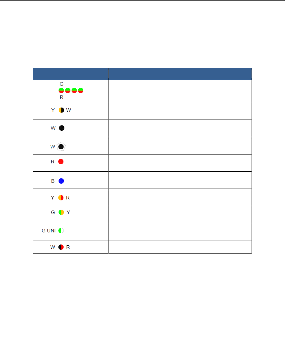
Legend and General Notes
Reference: AC 150/5340-30
The table below shows the lighting color symbols and associated letters that are used in images in the rest of
this chapter.
Edge lighting color code Description
Runway threshold / End lights
Green (G) / Red (R)
Runway edge light (see note 3)
Yellow (Y) / White (W)
Runway edge light
White (W)
Runway edge light (in-pavement)
White (W)
Runway threshold / End light
Red (R)
Taxiway edge light
Blue (B)
Runway edge light at displaced threshold
Yellow (Y) / Red (R)
Threshold / Runway edge lights at displaced threshold
Green (G) / Yellow (Y)
Runway threshold light with a unidirectional green
(G UNI)
Runway Centerline, LAHSO White (W) / Red (R)
Notes:
• Light fixtures for the lights identified in the color code chart are specified in AC 150/5345-46.
• White lights are shown as black.
• For an instrument runway, install yellow runway edge lights on the last 2000 ft. or one-half the runway
length, whichever is less.
• Pavement markings shown on the drawing in AC 150/5340-30 are for reference only.
AC 150/5340-1 describes the detailed marking specifications.
Chapter 2 - Airfield Lighting
A Quick Reference to Airfield Standards Updated January 2021 28
Airports Division
Runway Lighting Configuration (HIRL and MIRL Runways)
HIRL Precision Instrument Approach - Runway Centerline Not Shown for HIRL. Non-Precision Instrument
Approach for MIRL
2’ minimum – 10’ maximum from the runway edge (full strength pavement).
Longitudinal Spacing: 200’ maximum
At taxiway and runway intersections:
For HIRLs when the gap exceeds 400 feet install an in-pavement fixture to maintain uniform spacing.
CAT III operations require uniform spacing from threshold to threshold, not to exceed 200’. Install in-pavement
lights at intersections, as needed.
Chapter 2 - Airfield Lighting
A Quick Reference to Airfield Standards Updated January 2021 29
Airports Division
Runway Lighting Configuration (LIRL Runways and MIRL Visual Runways)
2’ minimum – 10’ maximum from the runway edge (full strength pavement).
Gaps between lights on a single side of the runway must not exceed 400 feet.
Chapter 2 - Airfield Lighting
A Quick Reference to Airfield Standards Updated January 2021 30
Airports Division
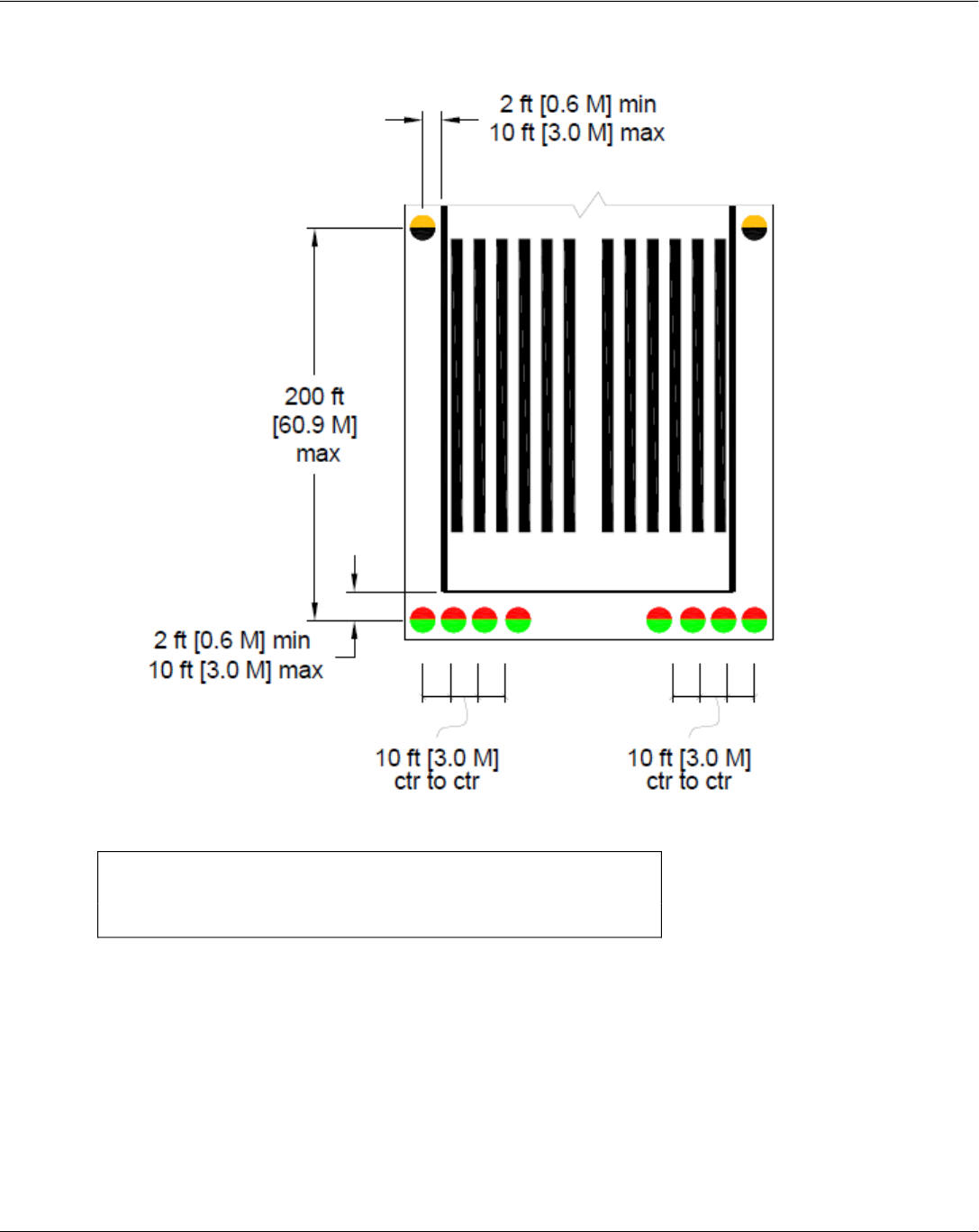
Threshold / Runway End Lights Installed with LIRLs and MIRLs
Legend: ctr = center
Note: Install six threshold lights on visual runways.
Chapter 2 - Airfield Lighting
A Quick Reference to Airfield Standards Updated January 2021 31
Airports Division
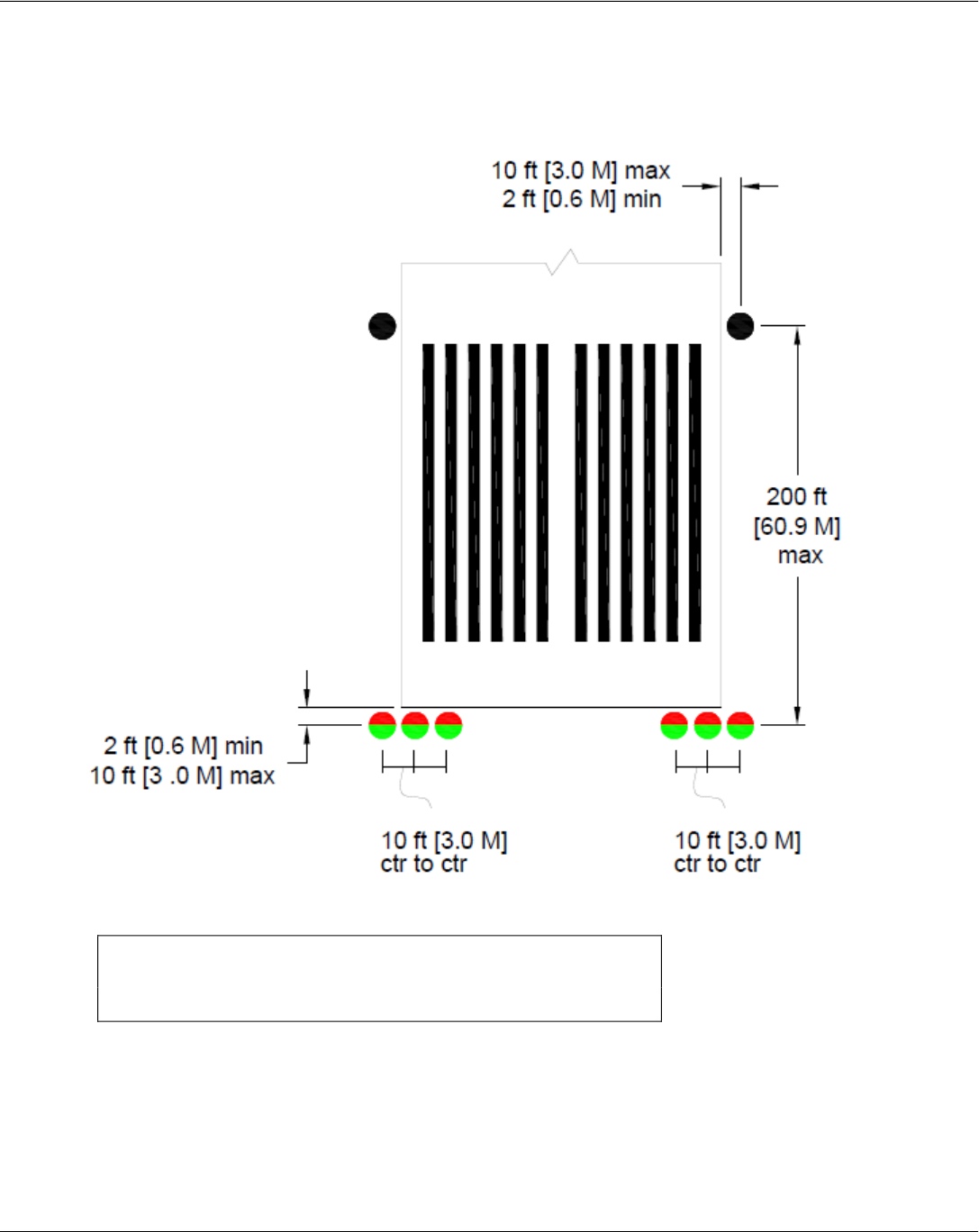
Threshold / Runway End Lights installed with HIRLs
Legend: ctr = center
Note: Install eight threshold lights on instrument runways.
Chapter 2 - Airfield Lighting
A Quick Reference to Airfield Standards Updated January 2021 32
Airports Division
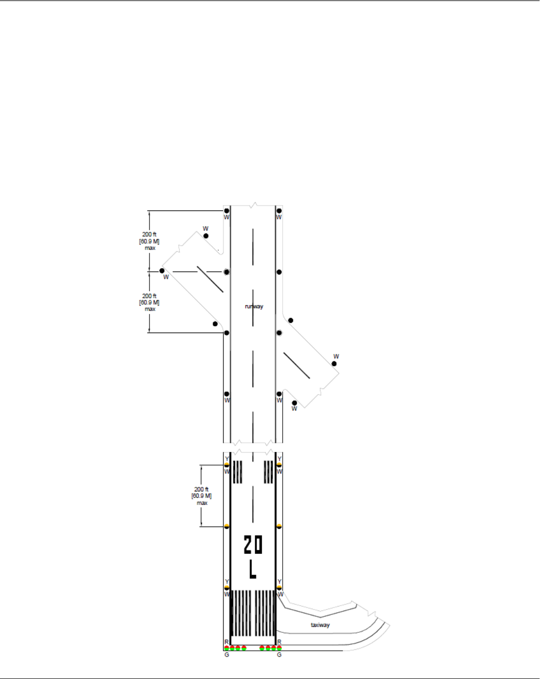
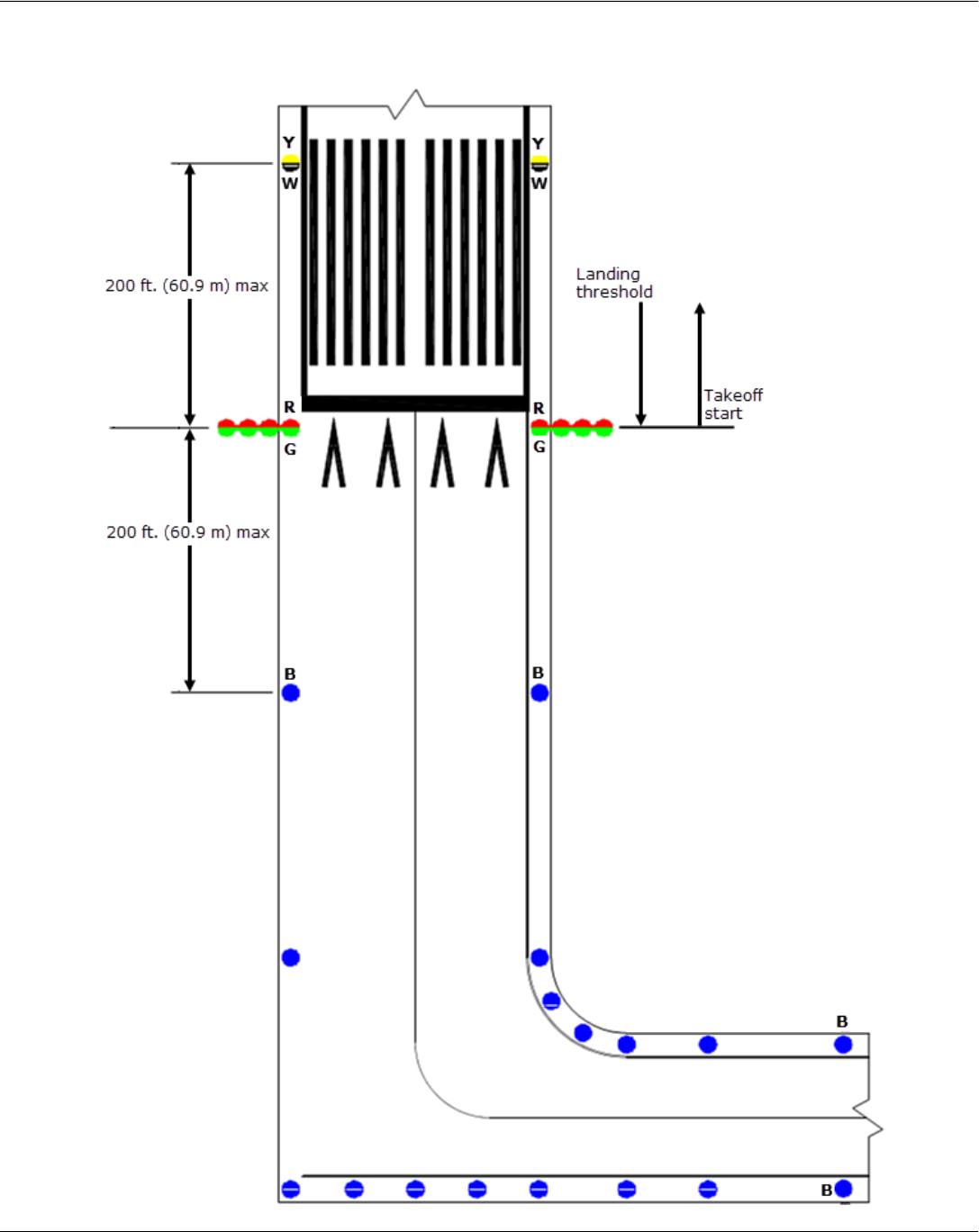
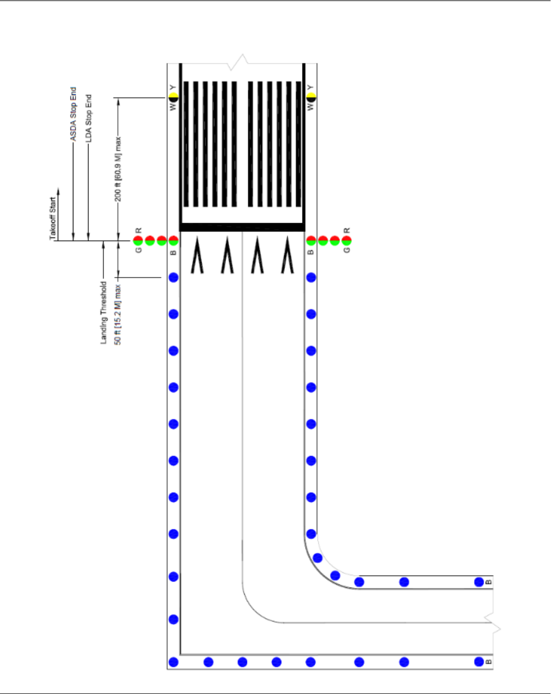
Runway with a Taxiway at the End
Chapter 2 - Airfield Lighting
A Quick Reference to Airfield Standards Updated January 2021 33
Airports Division
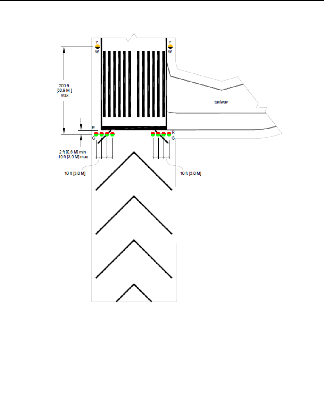
Runway with a Blast Pad
Chapter 2 - Airfield Lighting
A Quick Reference to Airfield Standards Updated January 2021 34
Airports Division
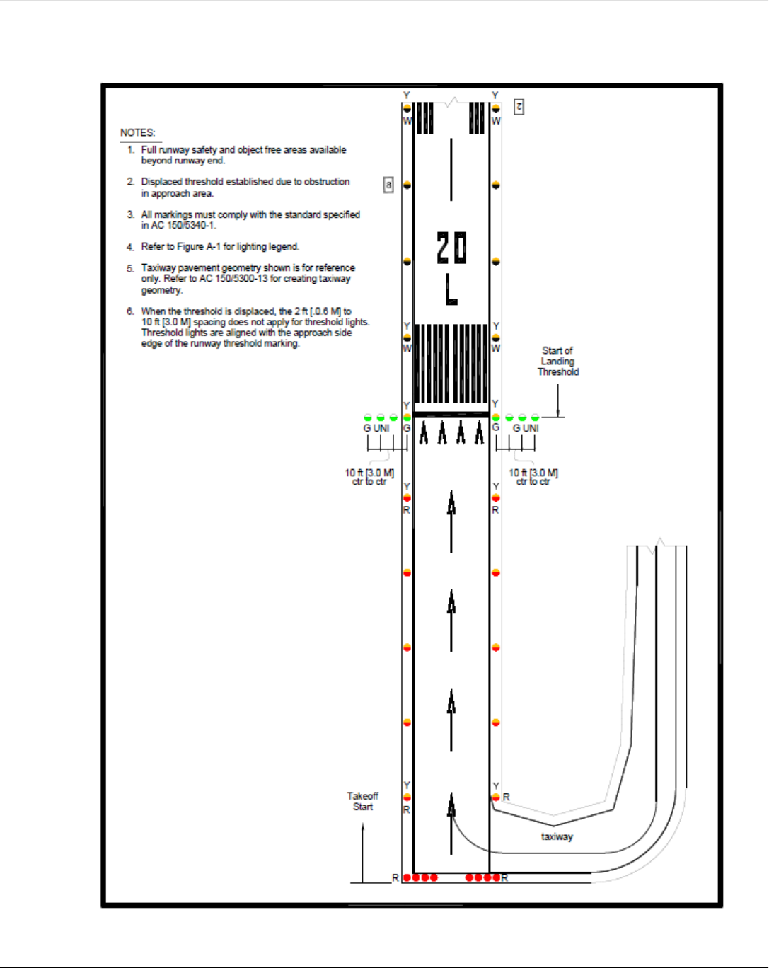
Lighting for Runway with a Displaced Threshold
Chapter 2 - Airfield Lighting
A Quick Reference to Airfield Standards Updated January 2021 35
Airports Division
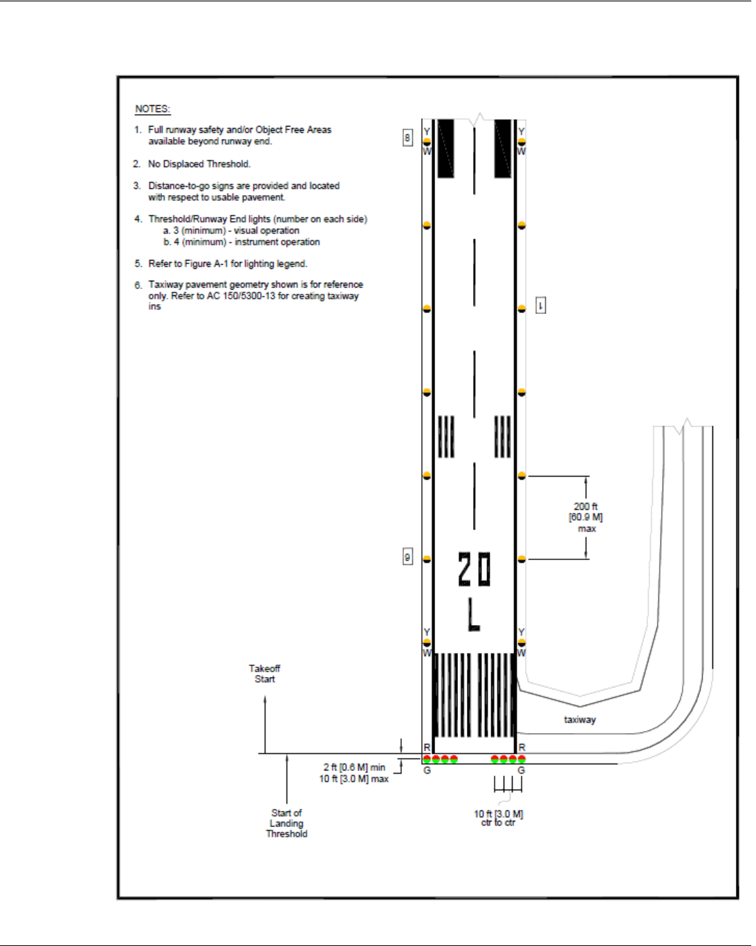
Normal Runway with Taxiway
Chapter 2 - Airfield Lighting
A Quick Reference to Airfield Standards Updated January 2021 36
Airports Division
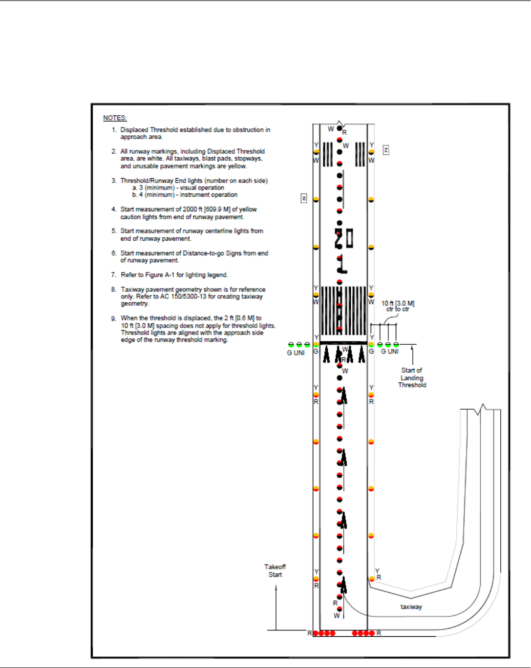
Lighting for Runway with Displaced Threshold
Greater than 700’
Note: Circuit centerline lights in the displaced area separately from the non-displaced area to permit turning-off
during landing operations (not required if approach lights are high intensity).
Chapter 2 - Airfield Lighting
A Quick Reference to Airfield Standards Updated January 2021 37
Airports Division
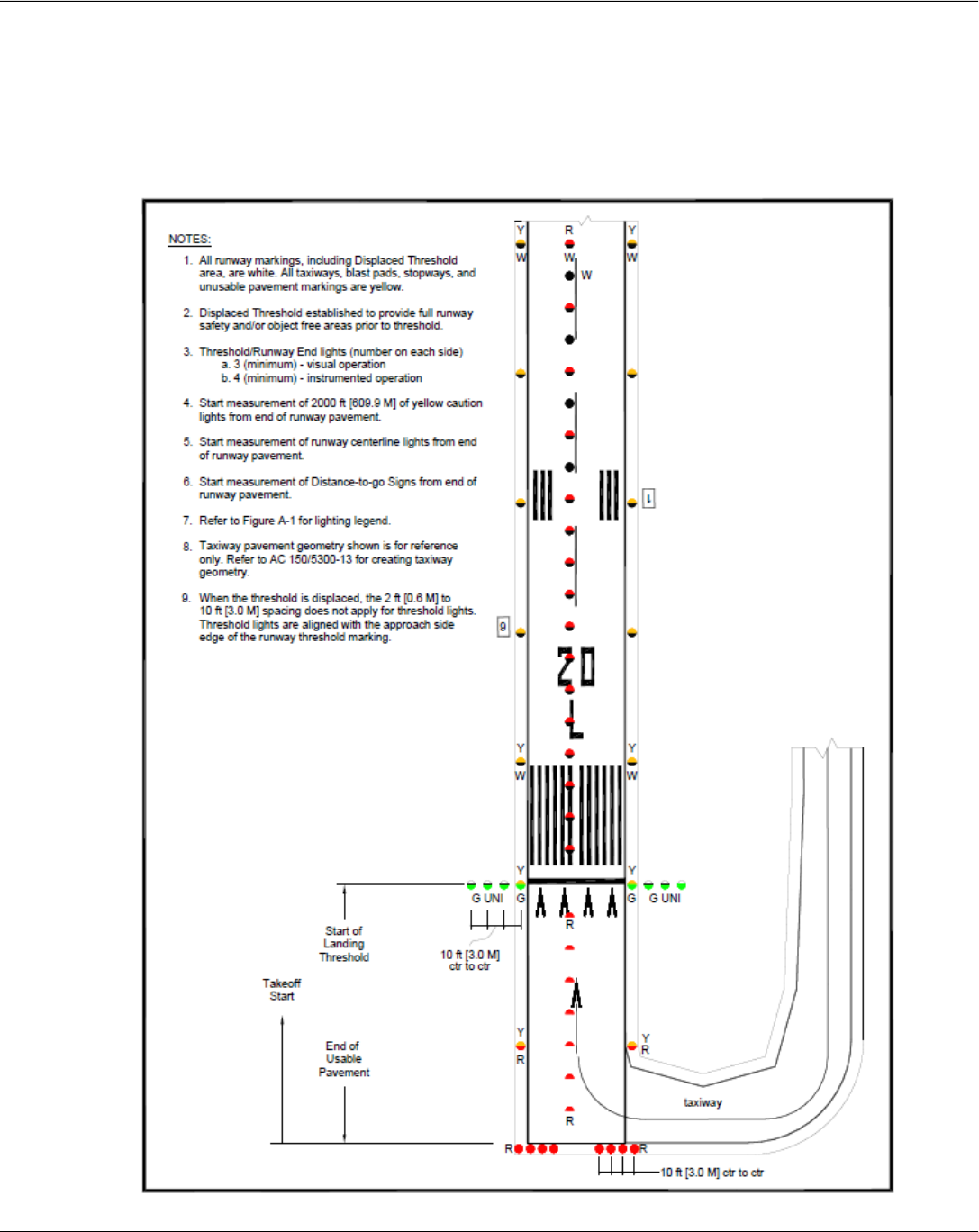
Lighting for Runway with Displaced Threshold
Less than 700’
Note: The centerline lights in the displaced threshold are blanked out in the approach direction.
Chapter 2 - Airfield Lighting
A Quick Reference to Airfield Standards Updated January 2021 38
Airports Division
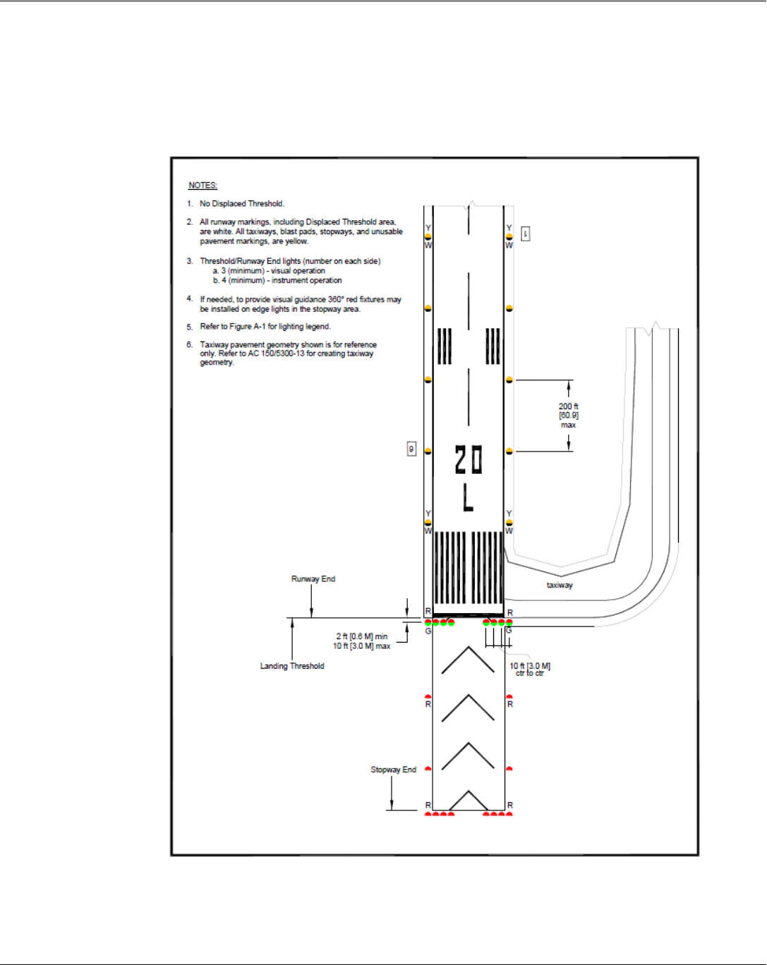
Lighting for Runway with Stopway
Note: Stopways look like blast pads but are considered full-strength pavement and are suitable to support
aircraft during an aborted take-off. If needed, to provide visual guidance, 360-degree red fixtures may be
installed on edge lights in the stopway area.
Chapter 2 - Airfield Lighting
A Quick Reference to Airfield Standards Updated January 2021 39
Airports Division
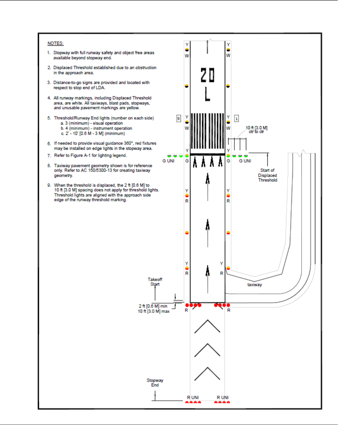
Lighting for Runway with Displaced Threshold and Stopway
Chapter 2 - Airfield Lighting
A Quick Reference to Airfield Standards Updated January 2021 40
Airports Division
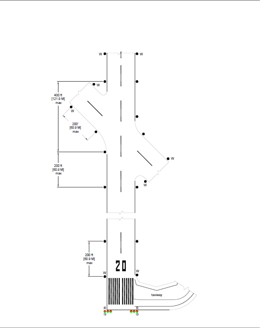
Runway with End Taxiway
Chapter 2 - Airfield Lighting
A Quick Reference to Airfield Standards Updated January 2021 41
Airports Division
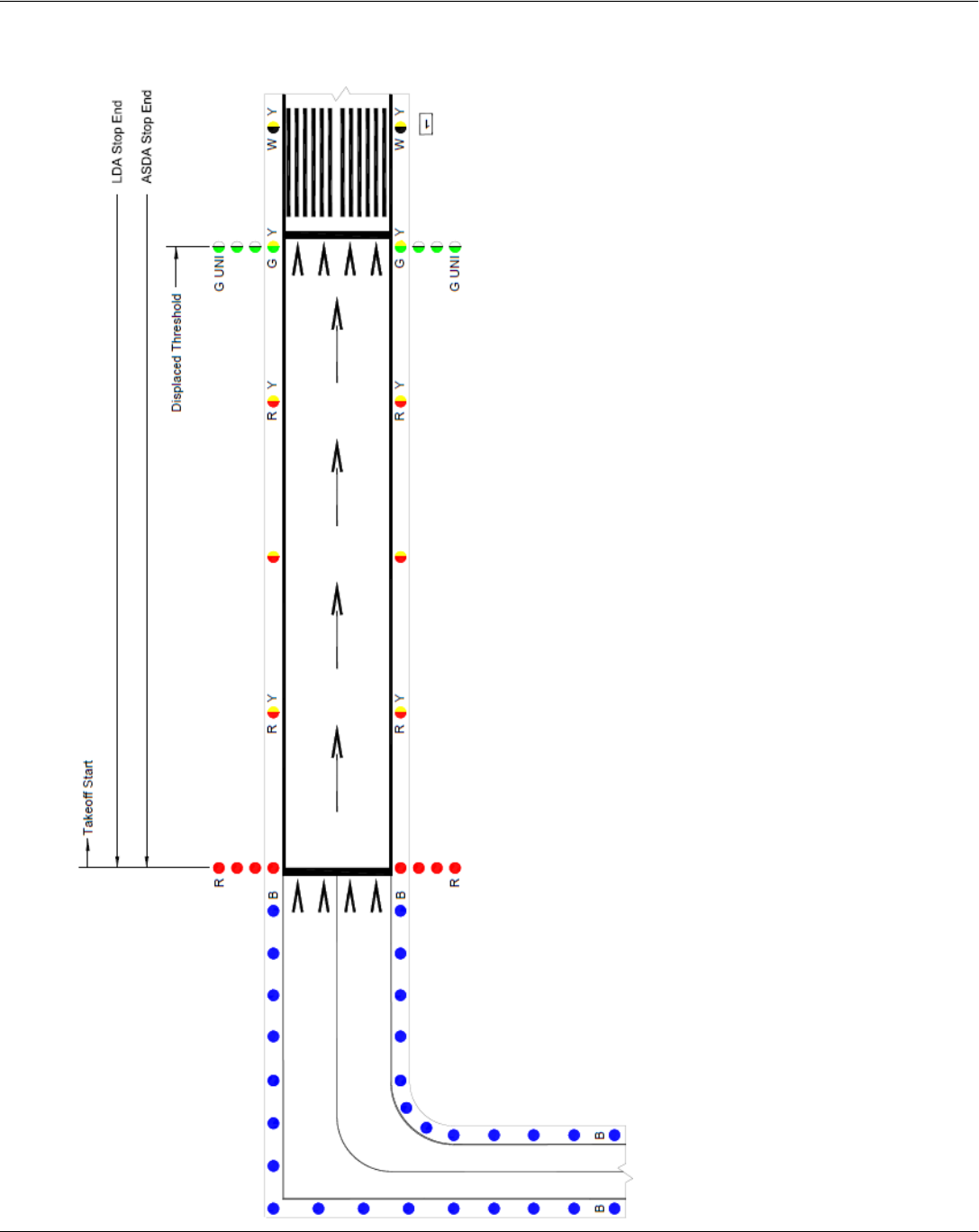
Lighting for Runway with End Taxiway and Displaced Threshold
Chapter 2 - Airfield Lighting
A Quick Reference to Airfield Standards Updated January 2021 42
Airports Division
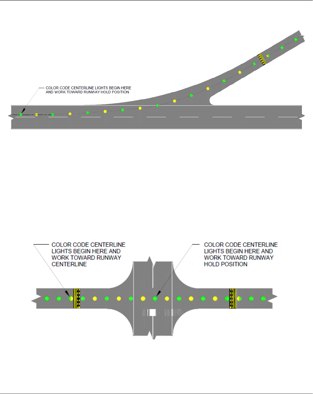
Color-coding of Exit Taxiway Centerline Lights
Notes:
• The first light on the runway is green. If there is an odd number of color-coded lights, the first two lights
should be green.
• The fixture used prior to the runway hold or ILS hold position must always be bidirectional: green when
approached from the taxiway direction and yellow when approached from the runway direction
(bidirectional).
• If there is an ILS critical area present beyond the runway holding position, the color-coded lights
continue to the ILS critical area holding position with the last yellow light similarly located beyond the
critical area holding position.
Chapter 2 - Airfield Lighting
A Quick Reference to Airfield Standards Updated January 2021 43
Airports Division
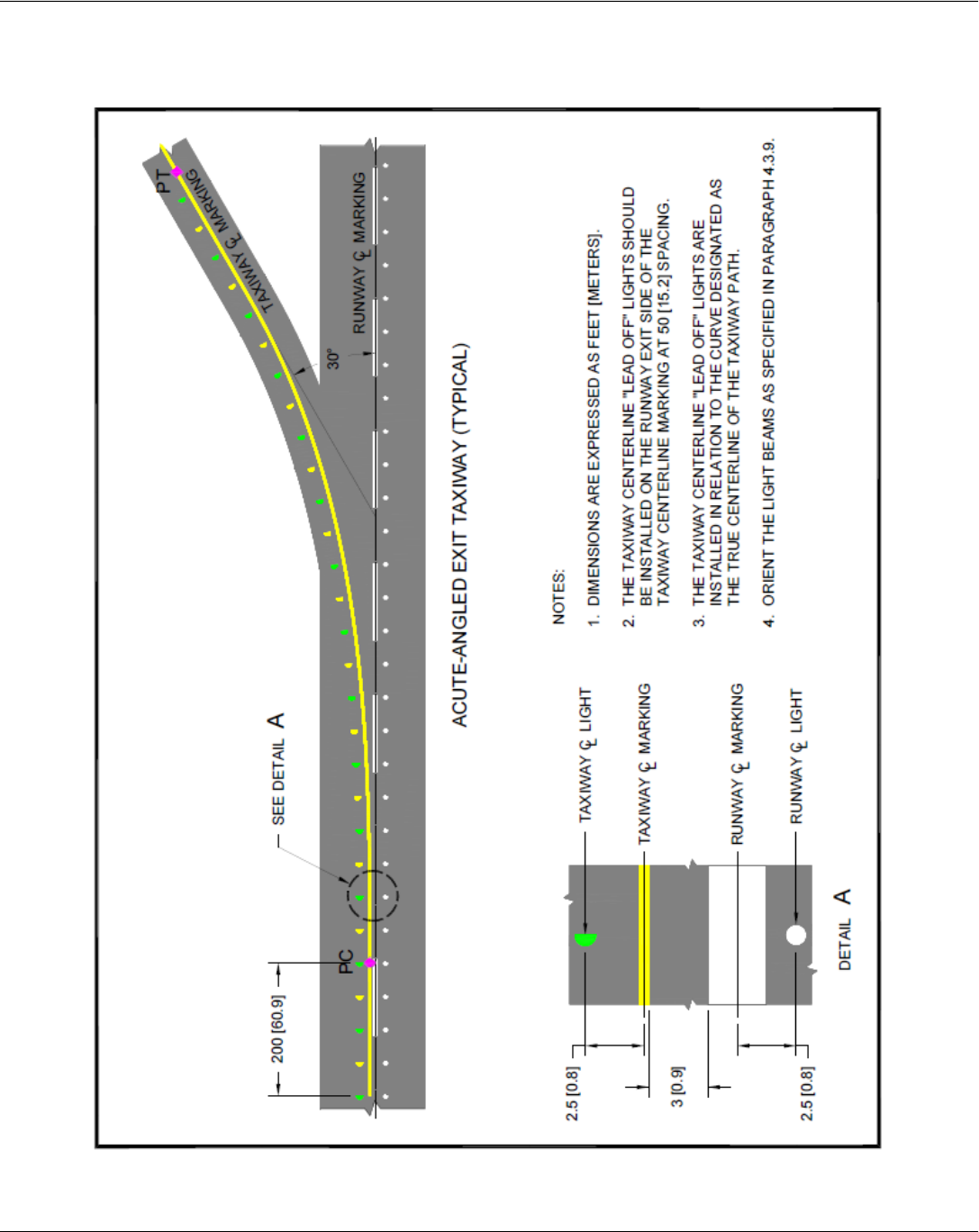
Taxiway Centerline Lighting Configuration for Acute - Angled Exits
Chapter 2 - Airfield Lighting
A Quick Reference to Airfield Standards Updated January 2021 44
Airports Division
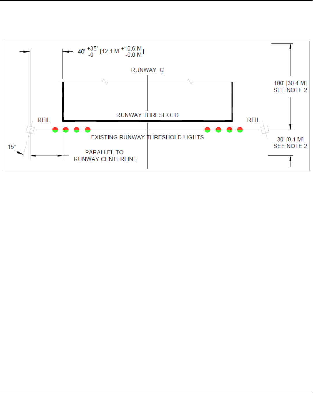
Typical Layout for Runway End Identifier Lights (REILs)
.
Notes:
• The optimum location for each light unit is in line with the runway threshold at 40 ft. from the runway
edge.
• A 100 ft. upwind and a 30 ft. downwind longitudinal tolerance are permitted from the runway threshold
in locating the light units.
• The light units shall be equally spaced from the runway centerline. When adjustments are necessary
the difference in the distance of the units from the runway centerline shall not exceed10 ft.
• The beam centerline (aiming angle) of each light unit is aimed 15 degrees outward from a line parallel
to the runway centerline and inclined at an angle 10 degrees above the horizontal. If angle adjustments
are necessary, provide an optical baffle and change the angles to 10 degrees horizontal and 20
degrees vertical.
• If REILS are used with VASI, install REILS at 75 ft. from the runway edge. When installed with other
glideslope indicators REILS shall be installed at 40 ft. from the runway edge unless there are concerns
with jet blast and wing vortices.
• The elevation of both units shall be within 3 ft. of the horizontal plane through the runway centerline.

Chapter 3 - Construction Safety
A Quick Reference to Airfield Standards Updated January 2021 45
Airports Division
Chapter 3 – Construction Safety
Reference: AC 150/5370-2
Safety Areas and Work Limits
• Construction activities are prohibited in safety areas while the associated runway or taxiway is open to
ANY aircraft. In the past, this prohibition applied only to air carriers.
• Only the airport operator may initiate or cancel NOTAMs on airport conditions, and is the only entity that
can close or open a runway.
• Stockpiled materials and equipment storage are not permitted within the runway safety area and object
free zone, and if possible should not be permitted within the object free area of an operational runway.
• Stockpiling material in the object free area requires submittal of a 7460-1.
• Open trenches or excavations are not permitted in the Taxiway Safety Area while the taxiway is open.
In rare circumstances where the section of taxiway is indispensable for aircraft movement, open
trenches or excavations may be permitted in the Taxiway Safety Area subject to the following
restrictions:
a. Taxiing speed is limited to 10 mph.
b. Appropriate NOTAMs are issued.
c. Marking and lighting standards that meet the provisions of paragraphs 2.18 and 2.20 of AC
150/5370-2 are implemented.
d. Low mass, low-profile lighted barricades are installed.
e. Appropriate temporary orange construction signs are installed.

Chapter 3 - Construction Safety
A Quick Reference to Airfield Standards Updated January 2021 46
Airports Division
Construction Reminders
• Establish procedures for the immediate notification of users and the FAA of any condition adversely
affecting safety.
• Develop a good, specific Construction Safety and Phasing Plan. Update during the project, as needed.
• Conduct periodic safety meetings with contractors and tenants.
• Continually review NOTAMs.
• Remember to include the aircraft rescue and firefighting department in all construction planning,
updates, and NOTAM notification.
• Penalties for non-compliance established in construction contracts are useful in ensuring contractor
compliance with safety procedures.
• Remember to use sweepers to control FOD from construction vehicles at movement area crossings.
• Inspect construction areas completely before opening/re-opening any airport surfaces.
• Use a “start-up/shut-down” checklist.
• Train, train, train, all employees and contractors who move around the Airport Operations Area.
• Continuously check construction barricades and other lighting during the night inspection.
• Coordinate all construction at the planning stage with the Air Traffic Control Tower to determine if a
Safety Risk Management Document (SRMD) is needed.
• Outbound destination signs are to be covered for closed runways.
• If a sign does not serve its normal function or provides conflicting information, then it must be covered
or removed to prevent misdirecting pilots.
• Information signs identifying a crossing taxiway continue to perform their normal function even if the
crossing taxiway is closed.
Chapter 3 - Construction Safety
A Quick Reference to Airfield Standards Updated January 2021 47
Airports Division
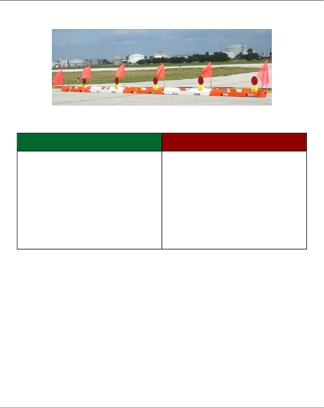
Construction Barricades
In Movement Areas
YES NO
• low mass and height
• weighted (if exposed to jet blast)
• easily collapsible
• retro-reflective orange and white in color
• frangible (if attached)
• weighted traffic cones
• orange/white flags attached
• red lights
(flashing or steady burning)
• railroad ties
• cement blocks
• tall barrels or metal drums
• Jersey (cement) barriers
• amber (yellow) lights
• wooden saw horses
• heavy, metal A-frames
• concrete filled buckets
ALL closed areas must be appropriately barricaded, especially taxiways and closed runway entrances.
• The spacing of barricades must be such that a breach is physically prevented barring a deliberate act.
For example, if barricades are intended to exclude vehicles, gaps between barricades must be smaller
than the width of the excluded vehicles; generally, 4 ft. Provision must be made for ARFF access if
necessary. If barricades are intended to exclude pedestrians, they must be continuously linked.
Continuous linking may be accomplished using ropes, securely attached to prevent FOD.
• Supplement barricades with signs; “No Entry" "No Vehicles" (optional)
• Barricades are not permitted in any active safety area.
• Even for closures of relatively short duration, close all taxiway/runway intersections with barricades.
The use of traffic cones is appropriate for short duration closures.
• All barricades adjacent to any open runway or taxiway, taxilane, safety area, or apron must be as low
as possible to the ground, and no more than 18 inches high, exclusive of supplementary lights and
flags.
Chapter 3 - Construction Safety
A Quick Reference to Airfield Standards Updated January 2021 48
Airports Division
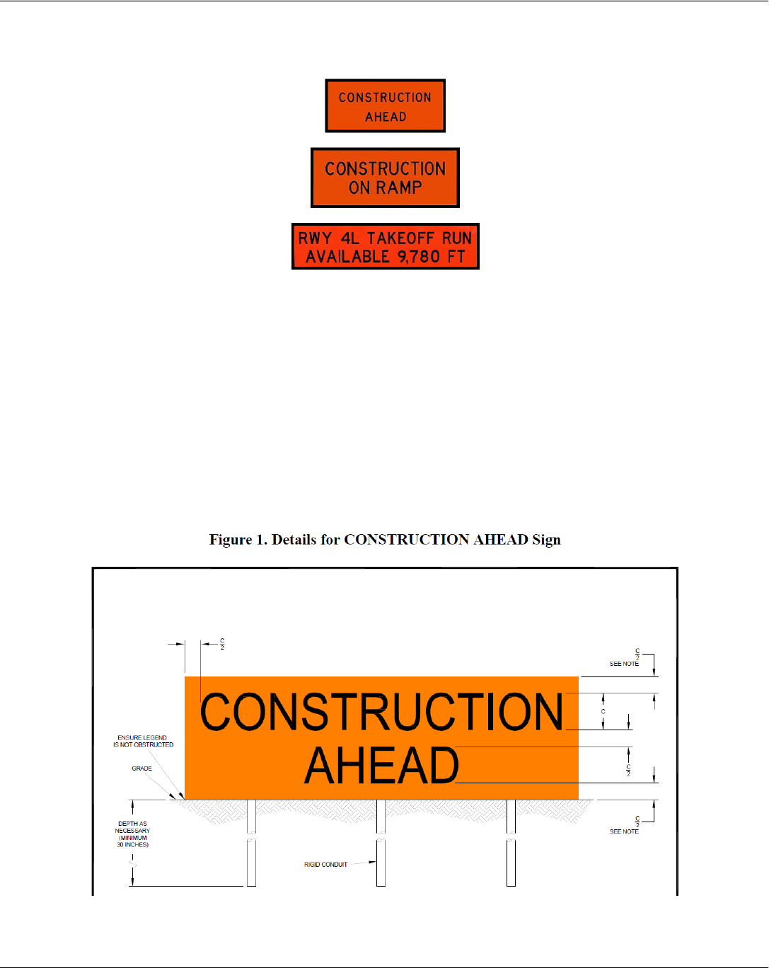
Temporary Signs
The airport operator may choose to introduce temporary construction signs with a black message on an orange
background.
• Signs that need to be located in a runway or taxiway safety area must be mounted on frangible
supports.
• Temporary signs must meet FAA Engineering Brief 93, Guidance for the Assembly and Installation of
Temporary Orange Construction Signs.
• Temporary signs must be included in the Construction Safety Phasing Plan.
• Signs must withstand 100 mph winds and jet blast without bending or changing shape.
• The background color of the signs must be fluorescent orange meeting the requirements of ASTM D
4956, Specification for Retroreflective Sheeting for Traffic Control, for Type III and Type IV sheeting.
Note: For 9-inch characters, reduce top and bottom borders by ¾-inch so the height of the sign face equals 30
inches.
Chapter 3 - Construction Safety
A Quick Reference to Airfield Standards Updated January 2021 49
Airports Division
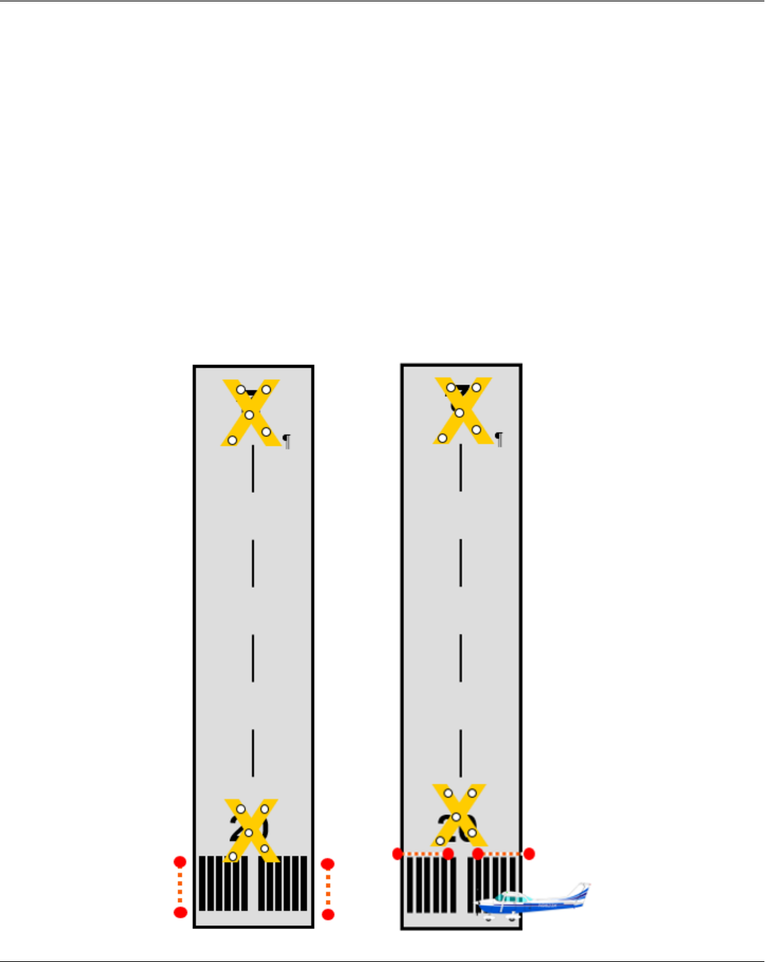
Temporarily Closed Runways
When temporarily closing runways:
• Turn off runway lights and approach lights.
• Turn off PAPIs or VASIs.
• Issue NOTAMs.
• Place an X at each end of the runway directly on or as near as practical to runway numbers. X’s can be
painted, double-layered snow fence, plywood, yellow-colored plastic, or other materials.
• If available, use lighted X’s, both at night and during the day. Lighted X’s are required at night if runway
lights are to remain on.
• If a lighted X is used, it MUST be illuminated at all times that it is on the runway.

Chapter 3 - Construction Safety
A Quick Reference to Airfield Standards Updated January 2021 50
Airports Division

Chapter 3 - Construction Safety
A Quick Reference to Airfield Standards Updated January 2021 51
Airports Division
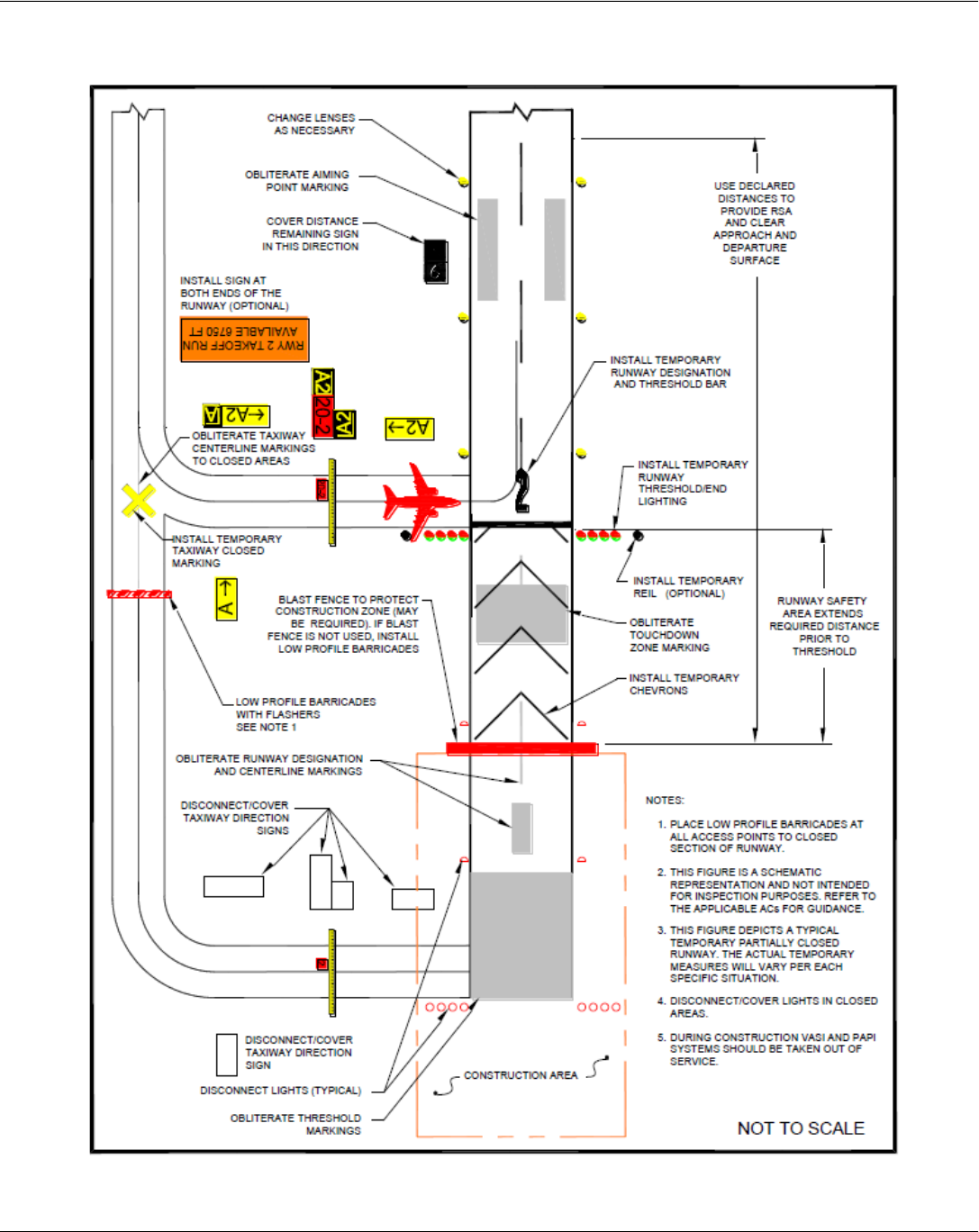
Partially Closed Runway
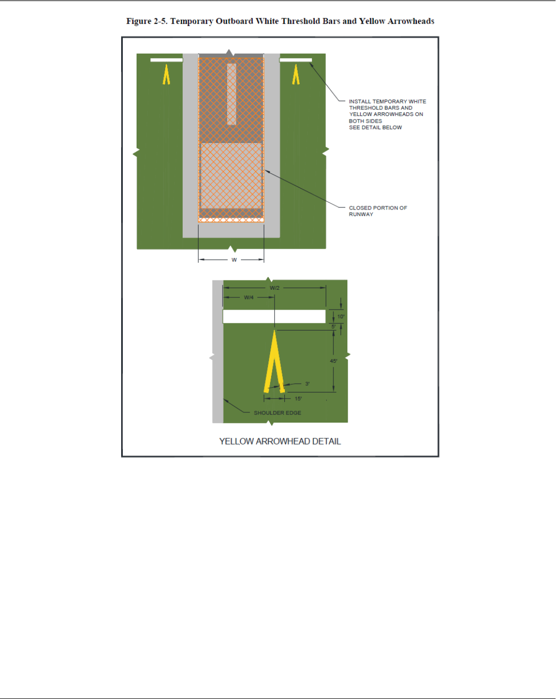
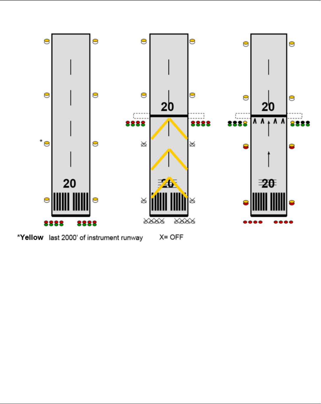
• Closed portions of the runway, not suitable for take-off or landing, must be marked with yellow chevrons.
These can be painted, double-layered snow fence, plywood, yellow-colored plastic or other materials.
• Runway numeral, in the closed portion, should be covered or removed.
• A temporary runway threshold bar should be provided. This can be painted at the new runway end or use
the elevated or flush type, mounted outboard of the pavement edge.
• Full runway safety area must be maintained for the relocated threshold or aircraft type should be restricted
as appropriate.
• Runway numeral should be painted at new threshold. Existing touchdown zone markings may remain.
• Issue appropriate NOTAMs regarding any nonstandard markings.
Chapter 3 - Construction Safety
A Quick Reference to Airfield Standards Updated January 2021 52
Airports Division
Chapter 3 - Construction Safety
A Quick Reference to Airfield Standards Updated January 2021 53
Airports Division
Temporary Partially Closed Runway
Chapter 3 - Construction Safety
A Quick Reference to Airfield Standards Updated January 2021 54
Airports Division
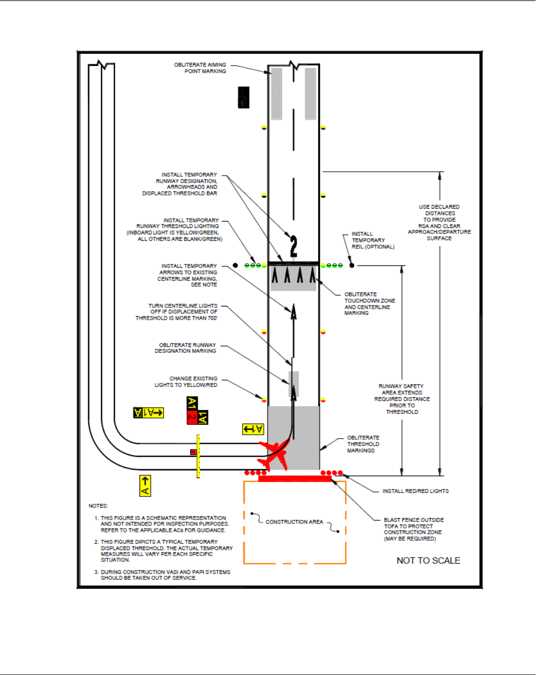
Temporary Displaced Threshold

Chapter 3 - Construction Safety
A Quick Reference to Airfield Standards Updated January 2021 55
Airports Division
Lighting Temporarily Relocated or Displaced Runway Thresholds
• Lighting in a closed area should be shut-off or covered.
• Removal of lamps from the fixture is not recommended since it may damage regulators.
• Temporary threshold light wires may run above ground with lamps weighted with sandbags or mounted on
frangible couplings.
• Temporary runway threshold/end light bases are to be installed at grade. The standard height above
ground for the fixtures is 14 inches.
• Yellow lights on instrument runways must be adjusted.
• Runway End Identifier Lights or relocated VASI/PAPI may be used.
• Distance Remaining Signs must be adjusted or covered.
• At towered, Part 139 airports, holding position signs are required to be illuminated on open taxiways
crossing to closed or inactive runways. If the holding position sign is installed on the runway circuit for the
closed runway, install a jumper to the taxiway circuit to provide power to the holding position sign for
Chapter 3 - Construction Safety
A Quick Reference to Airfield Standards Updated January 2021 56
Airports Division
nighttime operations. Where it is not possible to maintain power to signs that would normally be
operational, install barricades to exclude aircraft.

Chapter 3 - Construction Safety
A Quick Reference to Airfield Standards Updated January 2021 57
Airports Division
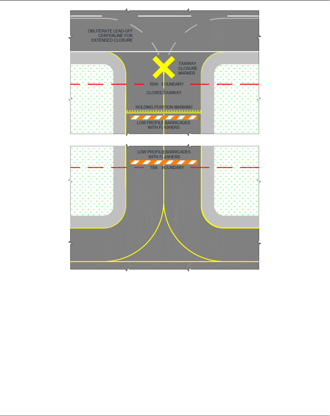
Temporary Taxiway Closure
• Taxiway lighting should be shut-off or covered.
• Taxiway centerlines that lead into closed areas should be removed if the project has a long duration.
• Place barricades outside the safety area of intersecting taxiways or runways.
• For runway/taxiway intersections, place an X at the entrance to the closed taxiway from the runway.
• Runway exit signs are to be covered for closed runway exits.
• If the centerline marking will be reused upon reopening the taxiway, it is preferable to paint over the
marking.
• Notices to Airmen (NOTAMs) must be issued.
CAUTION: Removal of lamps from the taxiway edge light fixtures is not recommended. This may cause
damage to the regulators. Shut off or cover them, instead.
Chapter 3 - Construction Safety
A Quick Reference to Airfield Standards Updated January 2021 58
Airports Division
Chapter 4 - Fuel Fire Safety
A Quick Reference to Airfield Standards Updated January 2021 59
Airports Division
Chapter 4 - Fuel Fire Safety
References:
• AC 150/5230-4
• Addendum for AC 150/5230-4, Aircraft Fuel Storage, Handling, Training, and Dispensing on Airports
• NFPA 407 - Standard for Aircraft Fuel Servicing- 2017 Edition
National Fire Protection Association
1 Batterymarch Park
P.O. Box 9101
Quincy, MA 02269-9101
1-800-344-3555
http://www.nfpa.org/catalog/

Chapter 4 - Fuel Fire Safety
A Quick Reference to Airfield Standards Updated January 2021 60
Airports Division
Fueling Supervisor and Personnel Training
Reference:
AC 150/5230-4
• Part 139.321 requires that at least one supervisor with each fueling agent must complete an aviation fuel
training course in fire safety that is authorized by the administrator prior to initial performance of duties or
enrolled in an authorized aviation fuel training course that will be completed within 90 days of initiating
duties and receive recurrent instruction at least every 24 consecutive calendar months.
• All employees who fuel aircraft, accept fuel shipments, or otherwise handle fuel must receive at least initial
on-the-job training and recurrent instruction every 24 consecutive calendar months from the trained
supervisor.
• The fueling supervisor must receive hands-on, hand-held fire extinguisher training within 60 days of
completion of the supervisory training course in fire safety, if not provided concurrently with the course.
• Records of supervisory and line service personnel training must be maintained by the fueling agent for 24
consecutive calendar months.
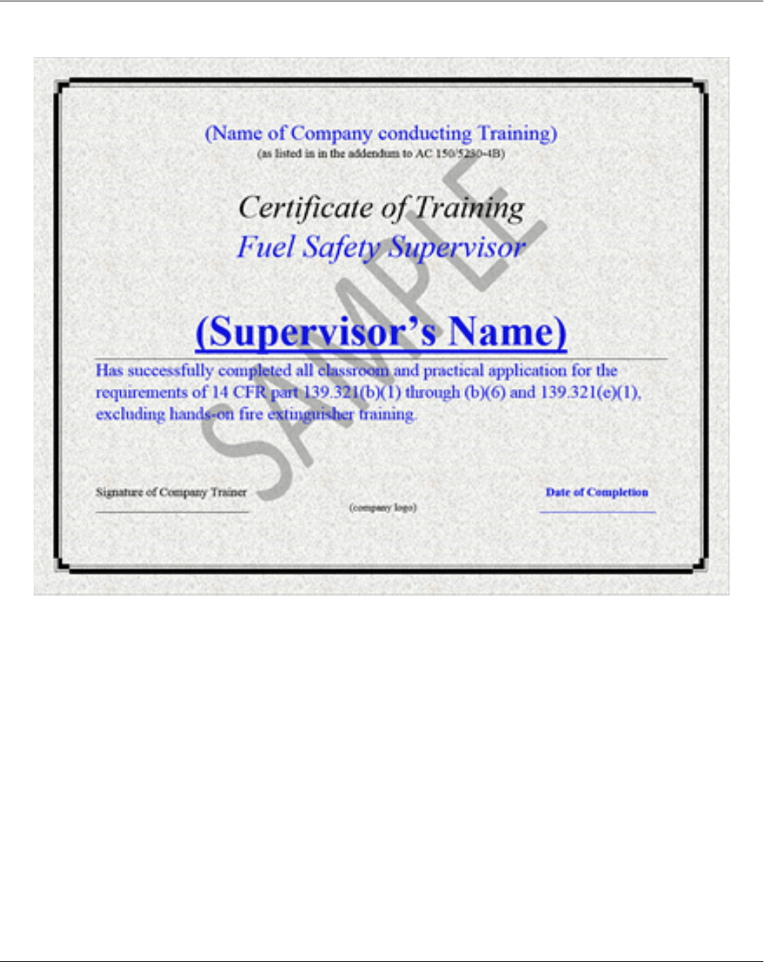
Fuel Training Certificates
• Certificates must differentiate between supervisor training and line service training
• Supervisor certificates must have the following wording: Name of the company doing the training, Name of
individual who completed “fuel safety supervisor” training, “Has successfully completed all classroom
and practical application for the requirements of 14 CFR part 139.321(b)(1) through (b)(6) and
139.321(e)(1)”, date of completion.
• Line training certificates must have the following wording: Name of the company doing the training, Name
of individual who completed “line fuel service” training, “Has successfully completed all classroom and
practical application for the requirements of 14 CFR part 139.321(b)(1) through (b)(7) and
139.321(e)(2)”, date of completion.
• Certificates of completion for courses that do not include hand held fire extinguisher training must include a
statement indicating “excluding hands-on fire extinguisher training.”
Chapter 4 - Fuel Fire Safety
A Quick Reference to Airfield Standards Updated January 2021 61
Airports Division
Sample Fueling Supervisor Training Certificate

Chapter 4 - Fuel Fire Safety
A Quick Reference to Airfield Standards Updated January 2021 62
Airports Division
Fueling Inspection – Aircraft Fuel Servicing Vehicles (SAMPLE)
Inspector: Fueling Agent: Date:
Vehicle 1: Truck number: ; Fuel type:
Vehicle 1: Truck number: ; Fuel type:
Vehicle 1: Truck number: ; Fuel type:
Enter rating codes: S =Satisfactory, U = Unsatisfactory, R = See remarks below.
Checkpoint
Vehicle 1
Rating
Vehicle 2
Rating
Vehicle 3
Rating
Fuel trucks/trailers parked 50’ from buildings and 10’ apart
Fuel trucks marked with operator name on both sides
No Fuel Leaks
Vehicle Exhaust System - Shielded/Leak free/spark arrestor if required
“No Smoking” sign on all 4 sides, No evidence of smoking, No ashtray/lighter
Flammability/Product signs all 4 sides of fuel trucks/carts
Hazmat placards all 4 sides of fuel trucks and carts
Bonding cables provided and clips. Plugs functional
Fuel Trucks - Two 40-B:C extinguishers on sides, No ABC DC extinguisher
Hydrant vehicles and carts - One 40-B:C extinguisher
Deadman Control for all nozzles. Not bypassed.
Integral system for nozzles to be stowed before moving fuel vehicle
Brake interlock system for bottom loading coupler/Over-wing nozzles
Emergency fuel shutoffs operable and properly placard -- 1 each side
Aircraft fueling hose: No blistering, cracking, saturation, or separation
Dry break couplers and adaptors are installed
Aviation fueling hose used. No Kinks
Explosion proof electrical. Light lens intact
Dome cover seals intact with forward mounted hinge
Truck cabinets have grating type flooring or open flooring
Proper Fueling Procedures Observed
N/A N/A
Remarks:
This Checklist is based on the 2017 NFPA 407 Fire Code for Airport Fueling Operations

Chapter 4 - Fuel Fire Safety
A Quick Reference to Airfield Standards Updated January 2021 63
Airports Division
Fueling Inspection – Airport Fuel Systems (SAMPLE)
Inspector: Fueling Agent: Date:
Enter rating codes: S =Satisfactory, U = Unsatisfactory, R = See remarks below.
Checkpoint
Jet A
Section
Rating
100LL
Section
Rating
Entrances to fueling areas posted with No Smoking signs
No evidence of smoking
All tanks, machinery, piping is bonded or grounded
Areas around tanks are free of weeds, trash or combustible materials
Diamond hazard placards installed on fuel tanks IAW AHJ
Emergency fuel shutoff provided for airport fueling system/Outside spill area
Emergency fuel shutoffs provided for each tank vehicle loading station
Proper EMERGENCY FUEL SHUTTOFF placards /7 ft. above grade
Emergency fuel shutoffs kept clear and tested every 6 months
Fuel servicing equipment properly maintained free of leaks
Procedures for prevention & control of spills and notification to fire department
Bonding connections available for loading stations
Deadman controls available for loading stations/Not bypassing Deadman
Dry break couplers and adaptors installed
Aircraft fuel hose/blistering, cracking, carcass saturation, separation, kinks
Fueling hydrants, pits, cabinets located 50’ from bldg. except loading bridges
40-B:C fire extinguishers at fuel storage area, usually at EFSO
40-B:C rated extinguisher at each fuel vehicle loading station
No A:B:C rated DC extinguishers within 500 ft. of aircraft operating areas
Wheeled extinguishers on aircraft servicing aprons at gates or 200 ft. apart
Explosion proof electrical equipment
Above ground fuel piping on aircraft movement area protected by barrier guard
Remarks:
This checklist is based on the 2017 NFPA 407 Fire Code for Airport Fueling Operations

Chapter 4 - Fuel Fire Safety
A Quick Reference to Airfield Standards Updated January 2021 64
Airports Division
Fueling Inspection – Self-Service Fuel Stations (SAMPLE)
Inspector: Fueling Agent: Date:
Type Fuel:
Enter the rating code: S =Satisfactory, U = Unsatisfactory.
Checkpoint Rating Remark
Entrances to fueling areas posted with No Smoking signs
Controlled access to dispensing equipment
All tanks, machinery, piping is bonded or grounded
Areas around tanks are free of weeds, trash or combustible materials
Diamond hazard placards installed on fuel tanks IAW AHJ
Emergency fuel shutoff provided/Incorporating a thermally actuated device
Emergency fuel shutoff located more than 20’ but less than 100’ from
dispenser
Proper EMERGENCY FUEL SHUTTOFF placards /7 ft. above grade
Dispensing devices located on an island/Protected by pipe bollards/guards
Dispensing equipment properly maintained free of leaks
Instructions provided for notification to fire dept. by emergency fuel shutoff
Bonding connections available for dispensing equipment
Deadman controls available for dispensing equipment
1 40 BC extinguisher at dispenser/1 40 BC at EFSO-No ABC DC
Aircraft fueling hose/No blistering, cracking carcass saturation, separation
Self-Fueling Station located 50’ from any buildings
Emergency Instructions posted in dispensing area
Operating Instructions posted
Explosion proof electrical equipment
Added Remarks:
This checklist is based on the 2017 NFPA 407 Fire Code for Airport Fueling Operations

Chapter 5 - Wildlife
A Quick Reference to Airfield Standards Updated January 2021 65
Airports Division
Chapter 5 - Wildlife
Reference: AC 150/5200-33; AC 150/5200-38; AC 150/5200-32
Each certificate holder must take immediate action to alleviate wildlife hazards whenever they are detected.
Triggering Events:
An air carrier aircraft experiences:
• Multiple wildlife strikes
• Substantial damage from striking wildlife
• Engine ingestion of wildlife; or
• Wildlife in size, or in numbers, capable of causing one of the above, is observed to have access to
airport flight patterns or movement areas.
A documented review of the Wildlife Hazard Management Plan is required following a triggering event
Wildlife Hazard Management Plan:
• Must meet all requirements of 14 CFR part 139
• Must be approved by the FAA and become a part of your Airport Certification Manual
• Must be reviewed and valuated every 12 consecutive calendar months or following a triggering event
(above)
• A training program conducted by a qualified wildlife damage management biologist must be provided to
all personnel responsible for implementing the plan
• Included copies of all Depredation Permits in the Wildlife Hazard Management Plan

Chapter 6 - Aircraft Rescue and Fire Fighting (ARFF)
A Quick Reference to Airfield Standards Updated January 2021 66
Airports Division
Chapter 6 - Aircraft Rescue and Fire Fighting (ARFF)
Reference: 14 CFR Part 139
ARFF Vehicles
The information below is for quick reference only.
Refer to 14 CFR part 139.317 for complete requirements.
ARFF
Index
Aircraft Length
(feet)
A
Less than 90
B
At least 90 but less than 126
C
At least 126 but less than 159
D
At least 159 but less than 200
E
At least 200
Index A. One vehicle carrying one of the following:
• 500 pounds of sodium-based dry chemical, halon 1211, or clean agent; or
• 450 pounds of potassium-based dry chemical and water with a commensurate quantity of AFFF to total
100 gallons for simultaneous dry chemical and AFFF application
Index B. Either of the following:
• One vehicle carrying at least 500 pounds of sodium-based dry chemical, halon 1211, or clean agent
and 1,500 gallons of water and the commensurate quantity of AFFF for foam production
• Two vehicles: One with the extinguishing agents specified for Index A and one vehicle carrying water
and AFFF so the total carried by both vehicles is at least 1,500 gallons.
Index C. Either of the following:
• Two vehicles: One vehicle carrying at least 500 pounds of sodium-based dry chemical, halon 1211, or
clean agent and 1,500 gallons of water and the commensurate quantity of AFFF for foam production
and one vehicle carrying water and AFFF so the total carried by both vehicles is at least 3,000 gallons.
• Three vehicles: One with the extinguishing agents specified for Index A and two vehicles carrying
water and AFFF so the total carried by all vehicles is at least 3,000 gallons.
Index D. Three vehicles:
• One with the extinguishing agents specified for Index A and two vehicles carrying water and AFFF so
the total carried by all vehicles is at least 4,000 gallons.
Index E. Three vehicles:
• One with the extinguishing agents specified for Index A and two vehicles carrying water and AFFF so
the total carried by all vehicles is at least 6,000 gallons.

Chapter 6 - Aircraft Rescue and Fire Fighting (ARFF)
A Quick Reference to Airfield Standards Updated January 2021 67
Airports Division
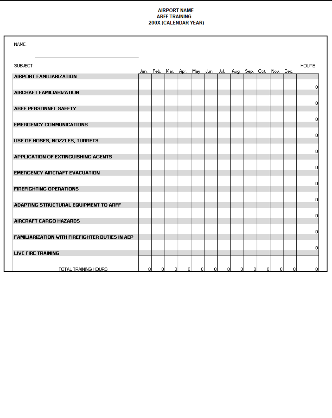
ARFF Training
References: AC 150/5210-17, 14 CFR part 139.319(i)(2)
The curriculum for initial and recurrent training must include at least the following areas:
• Airport Familiarization, including airport signs, marking, and lighting
• Aircraft familiarization
• Rescue and firefighting personnel safety
• Emergency communications systems on the airport, including fire alarms
• Use of the fire hoses, nozzles, turrets, and other appliances required for compliance with this part
• Application of the types of extinguishing agents required for compliance with this part
• Emergency aircraft evacuation assistance
• Firefighting operations
• Adapting and using structural rescue firefighting equipment for aircraft rescue and firefighting
• Aircraft cargo hazards, including hazardous materials/dangerous goods incidents
• Familiarization with firefighters’ duties under the airport emergency plan
• Live fire drill
Note: Any other subject area, as assigned in the Airport Certification Manual must be included.
Examples include Airport Safety Self-Inspection, Fuel Fire Safety Inspection, and NOTAM procedures.
Chapter 6 - Aircraft Rescue and Fire Fighting (ARFF)
A Quick Reference to Airfield Standards Updated January 2021 68
Airports Division

Chapter 7 - Pedestrians and Ground Vehicles
A Quick Reference to Airfield Standards Updated January 2021 69
Airports Division
Chapter 7 - Pedestrians and Ground Vehicles
References:
AC 150/5210-5
AC 150/5210-20
• Anyone with unescorted access to the Airport Operations Area must be trained
• Initial and recurrent training must include airport procedures, safety, work area limits, security, and
radio communications and must be airport-specific
• This training can be delegated to tenants and contractors but must be acceptable to and reviewed by
the airport operator and records must be kept
• Construction traffic should use only designated haul routes or roads
• All vehicles must be appropriately marked and lighted
• Aircraft always have the right of way!
PARK YOUR CELL PHONE(S) - DO NOT TEXT AND DRIVE!
Types of Incidents:
• V/PD - Vehicle or Pedestrian Deviation
• PD - Pilot Deviation
• OI - Operational Incident
Runway Incursion: Any occurrence at an aerodrome involving the incorrect presence of an aircraft,
vehicle, or person on the protected area of a surface designated for the landing and takeoff of aircraft.
Surface Incident: Unauthorized access to the movement area, excluding the runway

Chapter 8 - References
A Quick Reference to Airfield Standards Updated January 2021 70
Airports Division
Chapter 8 – References
FAA Advisory Circulars
Subject AC 150/
Airport Design 5300-13
Construction 5370-2
Design and Installation Details for Airport Visual Aids 5340-30
Foreign Object Debris Management 5210-24
Fuel Storage, Handling, and Dispensing 5230-4
Ground Vehicle Marking/Lighting 5210-5
Ground Vehicle Operations 5210-20
Landfill/ Waste 5200-34
Lighted ‘X’ 5345-55
Maintenance of Airport Visual Aids 5340-26
Markings 5340-1
Notice to Airmen (NOTAM) 5200-28
Precision Approach Path Indicator (PAPI) Systems 5345-28
Retro-reflective Markers 5345-39
Safety Management Systems (SMS) 5200-37
Self-Inspection 5200-18
Specification For Runway and Taxiway Signs 5345-44
Signs 5340-18
Specification Portable Runway and Taxiway Lights 5345-50
Wildlife 5200-33
Wildlife Biologist 5200-36
Winter Operations 5200-30
More Advisory Circulars are available online at:
http://www.faa.gov/airports/resources/advisory_circulars/
Aircraft Rescue Firefighting information:
https://www.faa.gov/airports/airport_safety/aircraft_rescue_fire_fighting/
Patrick Rogers, Lead Inspector, FAA Southern Region, prepared this Quick Reference
Revised January 2021 by John Fotiadis, Airport Certification Safety Inspector
