Take off locker
Locker
Locker
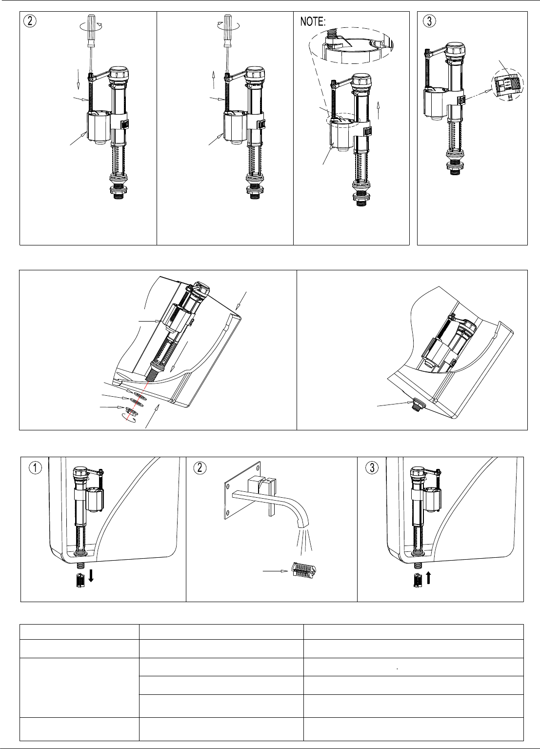
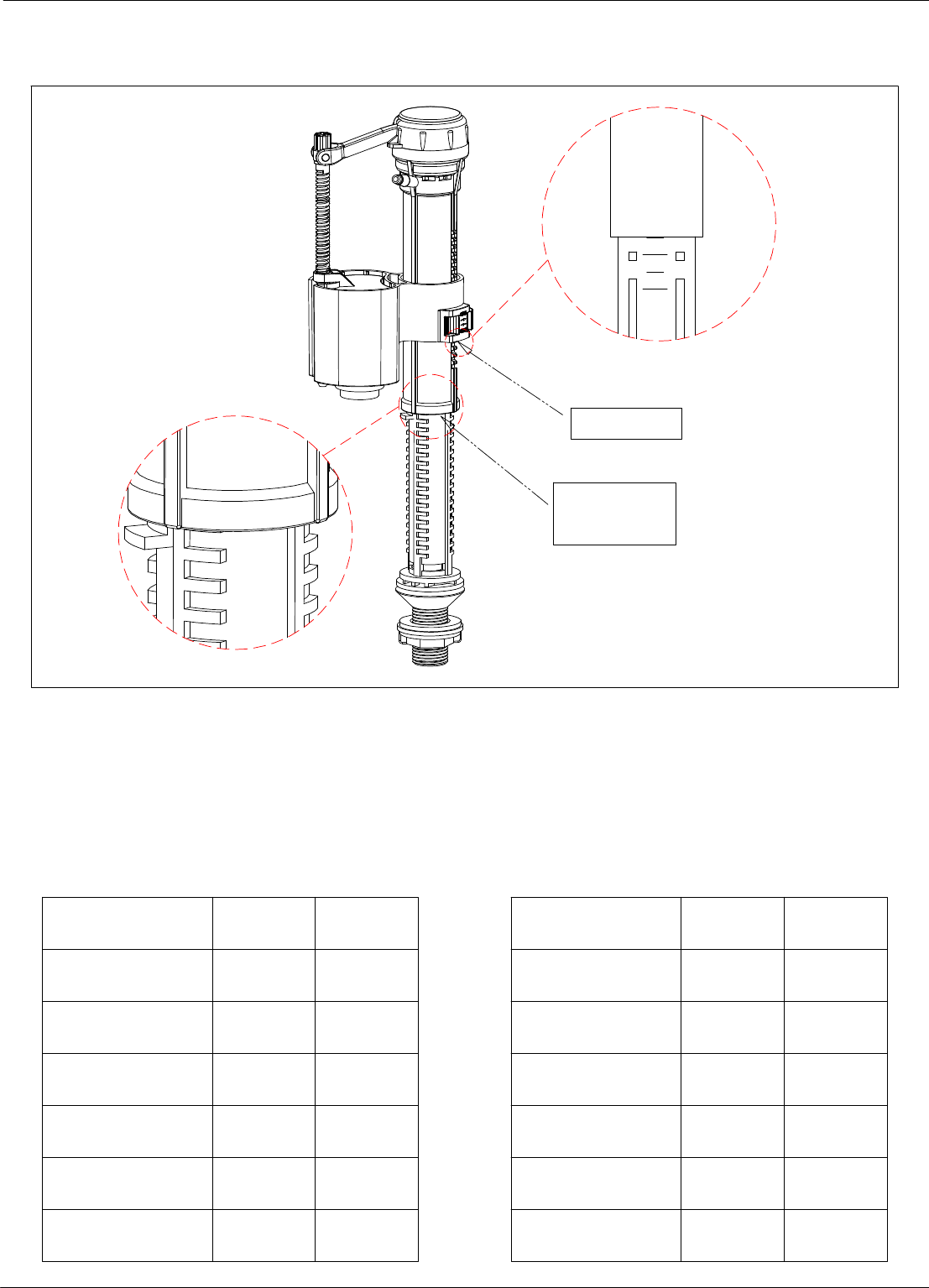
A: Major water level adjustment
Loosen the inlet body by
turning slightly anti-clockwise,
Adjust it up or down to correct
position and tighten clockwise.
Re-insert the locker
Slide the locker to "unlock" position,
Move the stop float up/down.
B: Minor water level adjustment
Locker
Stop
Float
F
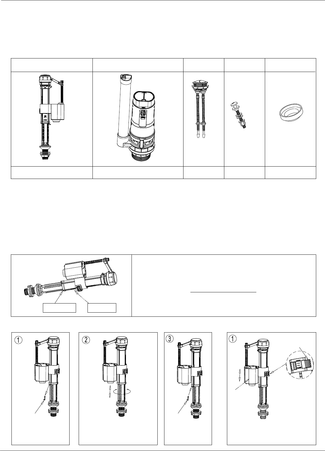
1x 1x 1x 2x 1x
Parts Supplied:
Inlet Valve Button
1 - 7
Flush Valve
Flush Cone
"Y" scale
Note:
The Inlet Valve should be adjusted for the particular cistern into
which it is being installed.
Please refer to the Adjustment Instruction on page 5 for the
X. Y settings.
The diagrams below show the detailed adjustment method.
1: Inlet Valve scale and adjustment settings
"X" setting
Do not use bleach or bleach based cleaning products in the cistern, as these will cause damage to the seals.
We cannot be held responsible or liable for any failure which results from the use of bleach based products.
Please read these instructions carefully to avoid damage to the valves, and to ensure correct installation.
Water temperature range +2C to +45C.
Water pressure 0.2 to 8 bar.
Bolt
Installation Instruction for
Dual Flush Cistern Fittings SP697
Inlet Valve Installation And Problem Solving
Leakage
Inlet Valve does not work
Clean the filter.
Tighten the nut.
The filter is blocked.
Water supply is closed.
Rubber Washer
Plastic Washer
Nut
Leakage
Incorrect water level
Problem
Solution
Open the water supply
Adjust the Water level correctly as per page 1 & 2.
Reconnect the Adjustment Rod,
and adjust the water level as per B on page 1 & 2.
The Stop Float has been over
adjusted beyond its operational range.
The Inlet Valve fixing nut
has not been tightened.
Incorrect adjustment.
Water supply is closed.
Reason
Cistern
Pull out the filter from the Inlet valve.
Filter
Insert the filter back into the Inlet valve.
4: Inlet Valve trouble shooting
2: Inlet Valve installation
Inlet Valve
3: Filter cleaning (Please clean periodically)
Clean by rinsing the filter.
Tighten the nut
2 - 7 F
Stop Float
Adjustment
Rod
Locker
To decrease the water level use
a screw driver to adjust the level
of the Stop Float ( as shown ).
The float should be lowered
To increase the water level use
a screw driver to adjust the level
of the Stop Float ( as shown ).
The float should be raised.
Slide the locker to
the "locked" position
Ensure the top surface of
Stop Float is in line with the
top surface of the Float Cup.
Stop Float
Float
cup
Stop Float
Adjustment
Rod
3 - 7 F
Half flush
float
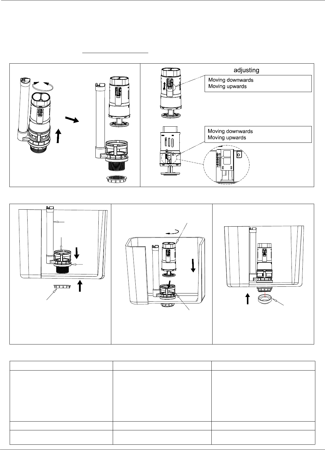
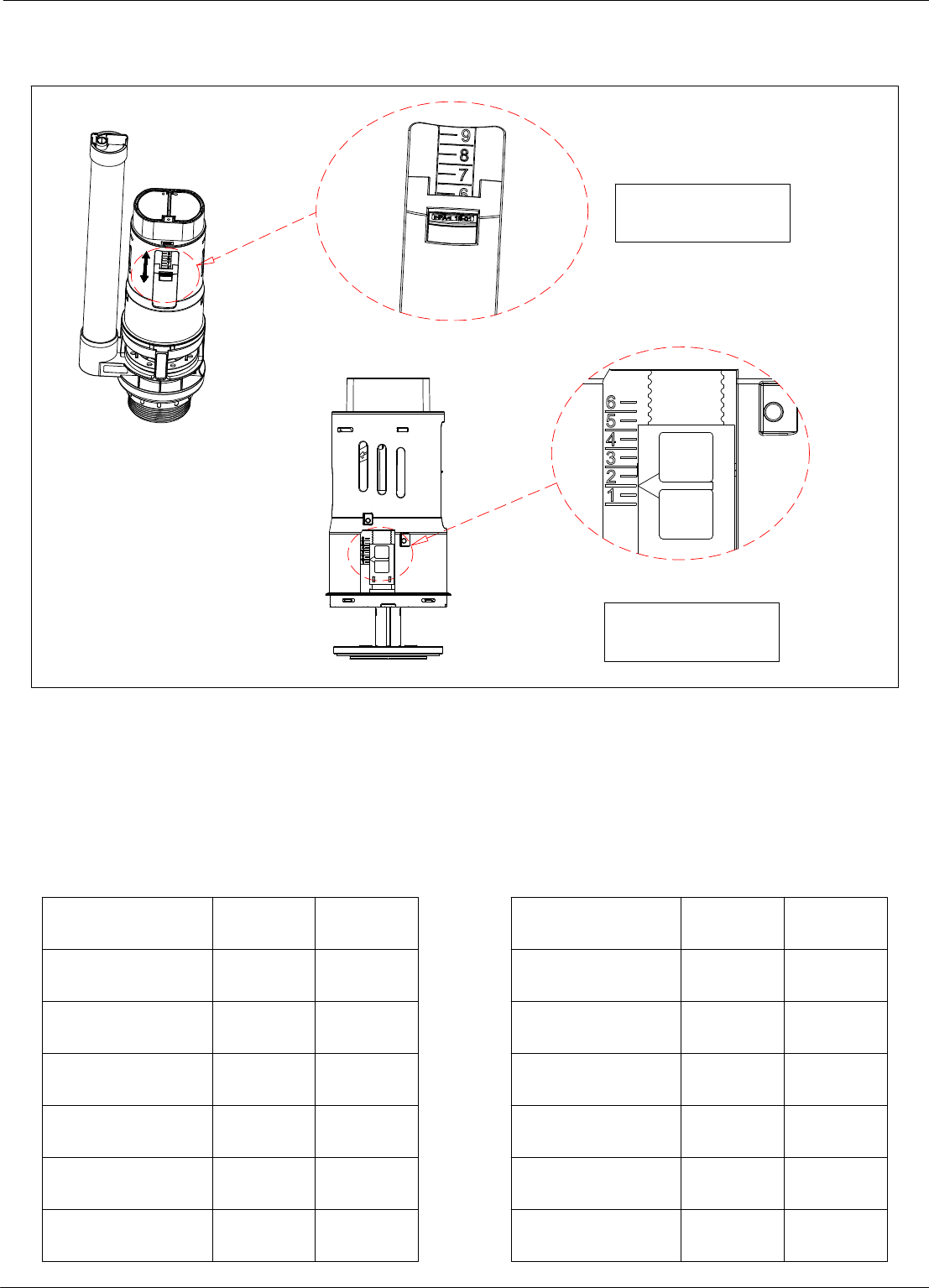
1: Flush Valve scale and adjustment setting
, flush volume increases.
, flush volume decreases.
3: Flush Valve trouble shooting
1.Install again according to the correct
installation procedure.
4.Take off and wash flush valve body.
Adjust the full flush adjustor or the half
flush float cup.
Full flush or half flush water level is
too high or too low.
Water level is adjusted incorrectly.
Push rod is too short.
4.Flush valve body is stuck.
3.Flush valve seat does not fit on the
flush valve body.
1.Incorrect installation.
No flush, low flush or half flush volume
Problem
Leakage
3.Install again, ensuring both surfaces
are clean for a water tight seal.
Reason Solution
Adjust the push rod length. (see page 4)
2: Flush Valve installation
Note: The Flush Valve should be adjusted for the particular cistern into which it is being installed.
Please refer to the Adjustment Instruction on page 6 for the full flush and half flush settings.
The diagrams below show the detailed adjustment method.
Flush Valve Installation And Problem Solving
Overflow pipe
Full flush adjustor
, flush volume increases.
, flush volume decreases.
Insert flush valve seat attached with
rubber washer into cistern flush hole.
Then install and tighten with the
fixing nut.
Flush valve seat
Rubber
washer
Fixing nut
Flush valve
body
Flush valve
seat
Push the flush cone over the fixing nut,
ensure that it is flat, and there will be no
leakage between cistern and pan.
2.The push rod is too long causing a
gap between the washer and the seat.
2.Adjust the push rod length.
(see page 4)
Flush cone
4 - 7 F
Cistern and Flush Button Installation
1: Install Close Coupled Cistern To Pan 2: Connect the water supply to the cistern
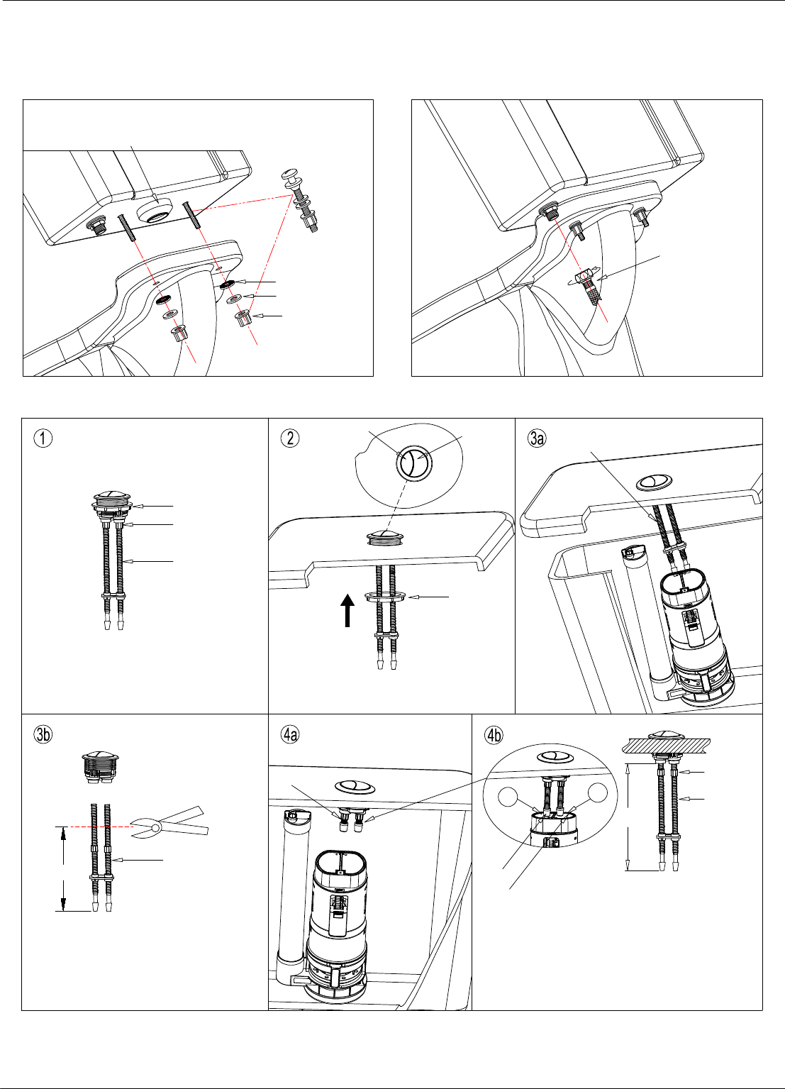
3: Install The Flush Button
Fixing nut
Lock nut
Take off the fixing nut.
Screw the lock nut to position.
Install the dual flush button onto the
cistern lid, and tighten the fixing nut.
Push rod
Push rod
Fixing nut
Lock nut
Push rod
A
Adjust the length of
A
by turning the push rod, and
remember to tighten the lock nut after finishing the
adjustment of the push rod
(A).
The final position should be that push rods just
come into contact with the flush valve, but should
not push down onto it unless the button is activated.
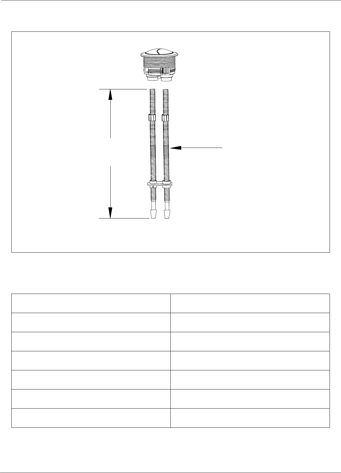
Loosen the lock nuts, and unscrew the
push rods to cut off the redundant section.
Please refer to the recommended length
"Z " of push rods for particular cistern on
page 7
.
Too long
Too short
4: After installation check that the full flush and half flush are working correctly.
Please consult the trouble shooting pages if there are any problems.
Half flush
Full flush
B
C
Full Flush Button - White
Z
Half Flush Button - Blue
Water supply
Fixing nut
Plastic washer
Rubber washer
* Please ensure the flush cone is in position before
installation. A thin bead of silicone should be applied
to the flush cone and the inlet hole of pan if necessary.
F
"Y" scale
Exposed
"X" steps
2
0
5 - 7
Note:
The above diagram is for reference only. In this example, X is set to 17 and Y is set to 3.
The inlet valve can be adjusted to suit the particular cistern, please refer to below tables for
the settings.
For adjustment method, please refer to the installation instruction on page 1 & 2.
Inlet Valve Adjustment Instructions
For 6L full flush and 3L half flush
Cistern code X Y
CC.1036 17 3
CM0007 20 3
15.B.27353 19 2
15.B.27349 17 2
SPH002 21 1
MAR.006 21 0
For 4.5L full flush and 2.6L half flush
Cistern code X Y
CC.1036 13 3
CM0007 17 3
15.B.27353 14 2
15.B.27349 16 2
SPH002 19 1
MAR.006 19 0
F6 - 7
Note:
The above diagram is for reference only. In this example, A is set to 6.5 and B is set to 2.
The flush valve can be adjusted to suit the particular cistern, please refer to below tables for
the settings.
For adjustment method, please refer to the installation instruction on page 3.
Flush Valve Adjustment Instructions
For 6L full flush and 3L half flush
Cistern code A B
CC.1036
6.5 2
CM0007 6.5 1.5
15.B.27353 7.5 1.5
15.B.27349
7
1.5
SPH002 7 1
MAR.006
7
1.5
For 4.5L full flush and 2.6L half flush
Cistern code A B
CC.1036 4.5 5
CM0007
6.5 5
15.B.27353 3.5 2
15.B.27349 3.5
4
SPH002
7
5
MAR.006
6
5
Half flush float
Should be set on
the "A" mark
Full flush adjustor
Should be set on
the "B" setting
F7 - 7
Recommended length of push rods
The push rods can be cut off to suit the particular cistern, please refer to below
table for the Z value.
Cistern code Z (mm)
CC.1036
CM0007
15.B.27353
15.B.27349
SPH002
MAR.006
Push rod
Z
197
197
159
207
181
200
